Hi OS, I would like to thank you for your CFA design you put up as a great generous X'mas gift for us all to share!
I like the BJT OPS designs for it's better use of the PSU and I have been worrking/fighting on a CFA with a 3EF lately myself in the LTspice. When yours came out I think I can abandon mine😀.
I dove into the LTspice and surely your design is quite tolerating in terms of component choices, although the simulated results tends to paint a rosy picture, due perhaps to the models employed.
I then put a Tian probe in the loop to exam the loop responses, and started to replace transistors with Cordell models. A big surprise came when the pre-drivers were replaced with same devices of Cordell models. The phase margin went from 75-deg to 60-deg, gain margin down from 18.3dB to 12.5dB, loop closes at 2.3MHz (vs 2.6Mhz as is) for unity gain. These are still good numbers to me, I'm not complaining at all. What really impressed me is how very greatly component modeling can change the scene in simulation. I will continue playing around this design and following your new thread hopefully soon to come out, and will be happy to make a PCB design for it.
Merry X'mas and a Happy New Year to all!
Only the actual built circuit's performance is what eventually counts. So, I am hoping all designs that look promising in SIM as CFA contenders get a chance to be measured and listened to as the final test.
Thx-RNMarsh
Thx-RNMarsh
Last edited:
I won't post here anymore ....
New thread will be the "SLEWMASTER" -CFA vs. VFA "rumble".
There be no "controversy" . Just better "stuff".
I will be open to any improvements to the CFA "front end".
I did get multiple PPM readings , but for most of the
audio spectrum... .001% was common (.0011 for 20k).
I don't think the PCB will "destroy" performance. With google and
the awesome designs at DIYA ... many good examples of layout.
I have had my hands on Halcro's ,stealth's , and a number of overbuilt-
overpriced amplifiers.
The flatpack leach or AAK's big symasym are examples of proper
layout.
BTW , I never really got any "big return" on my designs/layouts.
If I was to do the math , only 10 cents/hour. 😱
ALL the "badgers" work , the same for anything else I would submit.
Chill out , have a happy New year ...
OS
Hi OS,
I like your design and think your results are impressive. Hope you're not frustrated and not sure why you are starting a new thread. This has been a great thread, and very fast-moving. Not sure of the advantage of a new thread. I must admit I have had trouble keeping up with this one. I hope I'll be able to look more closely at your design and ask you some questions when I get a chance to.
Cheers,
Bob
CFA design -
😎🙂
Yes, stay and be a part of it's history making discoveries in CFA (OK so I exaggerate); Great group over here and we want all the good design input and debate there is to have here.... all in one place for the DIY'ers who are reading and who will be reading in the future. But, if it is just the construction/build/PCB/BOM part of a design, that would be better served IMO in another thread.
Thx-Richard Marsh
Hi OS,
I like your design and think your results are impressive. Hope you're not frustrated and not sure why you are starting a new thread. This has been a great thread, and very fast-moving. Not sure of the advantage of a new thread. I must admit I have had trouble keeping up with this one. I hope I'll be able to look more closely at your design and ask you some questions when I get a chance to.
Cheers,
Bob
😎🙂
Yes, stay and be a part of it's history making discoveries in CFA (OK so I exaggerate); Great group over here and we want all the good design input and debate there is to have here.... all in one place for the DIY'ers who are reading and who will be reading in the future. But, if it is just the construction/build/PCB/BOM part of a design, that would be better served IMO in another thread.
Thx-Richard Marsh
Last edited:
I agree with Bob and Richard on this one OS.
There will be the odd snipe. The trick is to ignore them and move forward. The more good practical designers we get and keep on ths thread, the more quickly we can move the SOTA forward wrt CFA. You are a quick study, and your CFA designs reflect that - thanks for your participation.
Merry Christmas/Happy Hols to everyone by the way!
Thanks guys .
I did start the thread. "SLEWMASTER" CFA vs. VFA "rumble".
I'll post on both threads , mainly design for this one and
"build" for the other one.
I've been digging in to Mr. Hawksford's papers , he is akin
to Tesla for audio amplifier design.
His cascode is amazing when combined with some of the better
VFA/CFA input stages. 😱
Design is ALL compromise ! "Try to get the most with the least"
Lazy cats "VSSA" is also a very good match for the
cascode. Adding a widlar to the cascode also has merit ....
I'm working on these "additions".
I really did not try to "shove" the cascode and triple down
everyone's throat (threadjack ?) , but they do have the lowest distortion vs.
complexity. My goal is to have a similar parts count/cost/complexity
as the "Badger" .... I have had little problem coaching error free
builds from that project despite the wide variations in sourcing.
I have a feeling my "next round" will even exceed this ...
I'm still "mentally visualizing the electrons " (Hawksford said this, too 😀)
OS
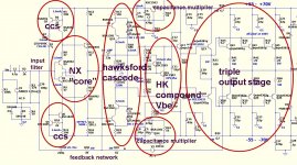
OS will you put your famous red circles around the parts of the amp to reflect the names and such of the specificites of the circuit. Like what part is the hawksford or vssa or any of the "additions" Thanks for edumencation, I do not feel like a so much of a newbie novice looking over your shoulder anymore. Sometimes I think I understand and then later I realize I did not. Like what is a "widlar"?
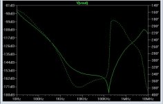
Here is a plot of CFA with AFEC.
I am putting this up because its a solid technique and especially suited to CFA's because of the very dramatic improvment in PSRR. You get about 20 dB improvement in 20 kHz distortion as well and DC servoing . . . sort of a CFA 'silver bullet'.
Expect to see another big 'bonsai' power amp employing AFEC in the next few months 😉
Attachments
I agree the Hawksford should be there, it has for the last 2 years been a part of my designs as well. (ref post 2902).
The design I have posted also has the advantage that it because of the way the housekeeping is made does not thermally drift in the input-stage and VAS (if you tie 4 transistors together) as well as the servo that can absorb .5V input-offset.
With nested /cherry) compensation it also shows remarkable distortion figures.
Why the 22 uF cap in the VBE..??
Bonsai aren't you afraid that using opamps in the feedback loop will make the amp sound like an opamp..??
Last edited:
WHat do you mean: "sound like an opamp" ?Bonsai aren't you afraid that using opamps in the feedback loop will make the amp sound like an opamp..??
I never found any common OPA 'signature'.
Each OPA has, or don't has its own signature. I used mostly OP260 for audio, as it was impossible, in blind tests, to make the difference with a strait wire (four circuit in serial inverting/non inverting with 10 & 1 gains).
Notice it was a CFA ;-)
Well, about what Bonsai call AFEC, i experimented the same idea, decades ago.
Gave-up for the following reasons.
- The comparator have phase turns at HF.(you'll try to find the fastest you can).
So, it will feedback negative or positive signal depending where is your comparing point. This lead to affect the bandwidth and distortion at HF and way below, introduce stability problems etc..
- It is very tricky to tune in order to get a a real null. I concluded it was inaccurate for mass production.
- It works like an increase of feedback ratio. This tend, on my subjective listening conclusions, at this time, and with the stuff i used, to reduce sound-stage, to bring 'tense' to the sound, some freedom, some ease lost. Sound was more fatiguing.
Don't take this as a definitive conclusion: I'm very aware to read real listening results from Bonsai experiments on this idea.
nb: When i working for hifi industry, i was in high concern with distortion numbers, as it help a lot the marketing department, and sells.
When it is about my own hifi system, i rely A LOT more on what i can listen as long as HD is decent. 🙂
This OPA question is interesting, as you can compare instant in/out. I found that relatively slow ppm OPAs, like the nice Scott's baby are not as transparent than some fast CFAs with lot higher HD.
Last edited:
WHat do you mean: "sound like an opamp" ?
I never found any common OPA 'signature'.
Each OPA has, or don't has its own signature. I used mostly OP260 for audio, as it was impossible, in blind tests, to make the difference with a strait wire (four circuit in serial inverting/non inverting with 10 & 1 gains).
Notice it was a CFA ;-)
I'm a no-opamp guy. You can record sound file like Mooly and PMA did on the other thread, and do a blind test through Foobar ABX. I don't believe there is a single opamp in the world I cannot ABX against direct.
Remember, fast CFA opamp requires special circuit and pcb track to sound "normal".
Here is a plot of CFA with AFEC.
I am putting this up because its a solid technique and especially suited to CFA's because of the very dramatic improvment in PSRR. You get about 20 dB improvement in 20 kHz distortion as well and DC servoing . . . sort of a CFA 'silver bullet'.
Expect to see another big 'bonsai' power amp employing AFEC in the next few months 😉
AFEC does seem to do well !
I don't hate op-amps , but there is a possibility they might
not have them in "Timbuktoo"😀
(below 1 - CFA) is what can be achieved with tight front end regulation.
I tried Afec (LT model) AND regulation = killer PSRR (below2).
I also tried AFEC on a VFA ..... what's PSSR ?? 😉
We also have the option of a separate regulated stage , this gives
results in between the 2 attachments.
OS
Attachments

Are-you sure ?I'm a no-opamp guy.
I would be VERY surprised if only one of your favorite records where recorded/mastered without a bunch of OPAs in the path 🙂
???Remember, fast CFA opamp requires special circuit and pcb track to sound "normal".
So many VF- OPAs replaced by OP260 in various mixing desks without any mod other than comp removal. Unity gain stable.
Last edited:
???
So many VF- OPAs replaced by OP260 in various mixing desks without any mod other than comp removal. Unity gain stable.
What I meant with "normal" is such that it cannot be distinguished from direct wire. I agree that CFA opamp (as presented by Mooly in the opamp shoot out thread) sounded like direct. High sr opamp is suitable for summing/mixing. It is superior in producing complex passage. But to perform as good as direct wire, I think a lot of thing to be done, including using boutique resistor in the FB path I presume.
I agree the Hawksford should be there, it has for the last 2 years been a part of my designs as well. (ref post 2902).
The design I have posted also has the advantage that it because of the way the housekeeping is made does not thermally drift in the input-stage and VAS (if you tie 4 transistors together) as well as the servo that can absorb .5V input-offset.
With nested /cherry) compensation it also shows remarkable distortion figures.
Why the 22 uF cap in the VBE..??
Bonsai aren't you afraid that using opamps in the feedback loop will make the amp sound like an opamp..??
Luckily you can switch it in and out easily (which is what I will do on my design)- so you can test your proposition 😉
However, I don't think it will affect the sound. The main feedback loop is the normal one. AFEC just nudges the feedback gently in the right direction to remove the errors.
However, I don't think it will affect the sound. The main feedback loop is the normal one.
But why risk it? Have you any success implementing it? I cannot see such success in commercial area. People tend to underestimate the actual audibility thresholds. How about no phase shift down to 5Hz? (just a blind proposal. LF inter modulation will be handled by rumble filter?)
BTW, there is the datasheet of OP260.
http://www.analog.com/static/imported-files/data_sheets_obsolete/544566978OP260.pdf
It resume most of the inputs in this thread about CFA.
Bonsai, have a look at the error cancellation application note schematic ;-)
- Because it is fun.
http://www.analog.com/static/imported-files/data_sheets_obsolete/544566978OP260.pdf
It resume most of the inputs in this thread about CFA.
Bonsai, have a look at the error cancellation application note schematic ;-)
- Because if you don't risk, you will never improve or initiate nothing.But why risk it?
- Because it is fun.
Last edited:
Yes, this argument again.Are-you sure ?
I would be VERY surprised if only one of your favorite records where recorded/mastered without a bunch of OPAs in the path 🙂
???.
Just because you have used noisy DAC, it doesn't mean you can use noisy amplifier.
- Home
- Amplifiers
- Solid State
- CFA Topology Audio Amplifiers