We had this discussion previously.1. The Williamson tube amplifier and most others had the negative feedback connected to the cathode of the input stage. Does this make it a CFA?
2. The early solid state amplifiers had the negative feedback connected to the emitter of the fist-stage transistor. Did this make them CFAs?
3. I prefer solid state amplifiers with JFET input stages. I have not seen any CFAs here with JFET inputs. Are JFET inputs not compatible with CFAs?
I ask these questions in the spirit of the broader view of what is a CFA in this thread, as opposed to the more narrow technical definition that has sometimes been cited here.
My answer was: http://www.diyaudio.com/forums/solid-state/240712-cfa-topology-audio-amplifiers-135.html#post3741535
and: #2576
Bonsai point of view is: www.diyaudio.com/forums/attachments/solid-state/387904d1387160549-cfa-topology-audio-amplifiers-cfa-vfa-feedback-modes_summary.pdf
and its definition: http://www.diyaudio.com/forums/solid-state/240712-cfa-topology-audio-amplifiers-29.html#post3737658
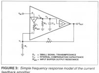
The description by Analog device can be found here:
http://www.analog.com/static/imported-files/data_sheets_obsolete/544566978OP260.pdf
You can also refer to the mark Alexander paper:
http://www.analog.com/static/import...tes/58052492001115525484056221917334AN211.pdf
I Believe Richard Marsh has its own precise but more restrictive idea on the question, but he was not very talkative about.
Scott Wurser was very silent about, despite he is part or witness of the AD history, leader in CFA designs in OPAs industry.
I advocate my position this way: it is better for everybody understanding to define a "Topology" and consider bad implementations of it as 'non optimal'.
There is no breaking point where you can consider the 'current on demand' no more at work, or to begin to think in a voltage point of view instead of current.
There is no breaking point where the bandwidth limitation in the feedback loop due to emitter capacitance and feedback impedance push an amp away from CFA because it limit slew-rate or bandwidth.
For me, as long as feedback is applied at the output of a loaded input buffer, with no active device in the feedback path, and signal fed to the next stage is produced by some kind of a current mirror (resistance from collector/drain/anode to rail is one) , it is CFA.
Input stage can be anything (FET, BJT, TUBE, OPA, buffer).
So, my answer to all your questions will be yes.
That is a personal point of view, we definitively need to produce a non controversial definition on witch everybody can agree here and elsewhere (is-this possible ?)
I believe you're good at this.
Last edited:
3. I prefer solid state amplifiers with JFET input stages. I have not seen any CFAs here with JFET inputs. Are JFET inputs not compatible with CFAs?
Is Nelson's F5 not a CFA? With exact input stage as most CFA here, a Jfet input has been used with darlington output.
I know we depend on symmetry behavior with this CFA circuitry, and Jfet are not matched, but I think that's not the main issue, especially with lateral o/s.
According to my previous definition, it is.Is Nelson's F5 not a CFA? With exact input stage as most CFA here, a Jfet input has been used with darlington output.
The input stage is a buffer loaded by 10 Ohms. Here is applied the feedback. The Drain to rail resistances are current sensors, giving some voltage gain depending to the drain/source resistances ratio.
After the input stage, we are free to add any stage we want to provide voltage and/or current gain to the loop, in the exact manner VFA behave.
Here, the output stage is implemented in common drain to reverse the phase as a traditional VAS do before a common source/common emitter OPS.
Impossible to imagine simpler.
(I love this Guy, despite i never met him, and believe his absence in this thread is a miss for all of us 🙂
Member
Joined 2009
Paid Member
I ask these questions in the spirit of the broader view of what is a CFA in this thread, as opposed to the more narrow technical definition that has sometimes been cited here.
+1
'CFA' a term that is in 'popular' use. If you try to define CFA you will then ascribe properties to such amplifiers that fits a narrow definition yet there will be non-CFA topologies that share these properties and you will unnecessarily narrow your perspective. In other words, 'CFA' is a meme and an attempt to define it here will eventually be out of date.
1. The Williamson tube amplifier and most others had the negative feedback connected to the cathode of the input stage. Does this make it a CFA?
2. The early solid state amplifiers had the negative feedback connected to the emitter of the fist-stage transistor. Did this make them CFAs?
3. I prefer solid state amplifiers with JFET input stages. I have not seen any CFAs here with JFET inputs. Are JFET inputs not compatible with CFAs?
I ask these questions in the spirit of the broader view of what is a CFA in this thread, as opposed to the more narrow technical definition that has sometimes been cited here.
---------------------------------------------------------------------------------
The answere to 1,2 is No. Should call them something else.
The jfet input is a natural and I would think would soon show up here in SIM results.
BUT, since the question keeps coming up about what is a CFA, I am willing to call anything a CFA as long as others know what topology looks like when it is called CFA.
The IC industry has no problem designing VFA and CFA circuits and calling them as such. There IS a difference.... much of the early part was describing the CFA topology. Readers are referred to the front end of this thread. I'm going to bed.
Thx-RNMarsh
Last edited:
+1
'CFA' a term that is in 'popular' use. If you try to define CFA you will then ascribe properties to such amplifiers that fits a narrow definition yet there will be non-CFA topologies that share these properties and you will unnecessarily narrow your perspective. In other words, 'CFA' is a meme and an attempt to define it here will eventually be out of date.
😎🙂
Sounds about right.
3. I prefer solid state amplifiers with JFET input stages. I have not seen any CFAs here with JFET inputs. Are JFET inputs not compatible with CFAs?
Cheers,
Bob
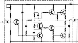
I am not sure did I presented this amp here already, but this one I simulated some time ago.
BR Damir
Attachments
Is this real life or sim OS?
I do not get past 1.2MHz in real life. Only if i lower VAS gain!
1.2mhz to 1.5 mhz is the VFA upper limit !
These alien CFA's play by different rules.
4.7mhz is where I can get 640V/us(10p). Slight overshoot at this plot.
Absolutely overkill , 47p gives 2.5mhz 250v/us .. this will be the
design target.
PS - Every thing I have ever simulated with KSA992/Ksc1845 - Ksa1381/ksc3503
has almost perfectly been realized in the real build. oscilloscope readings/DMM readings ...
I WOULD NOT waste my time designing a PCB for a "dud" ...
OS
Attachments
Last edited:
1.2mhz to 1.5 mhz is the VFA upper limit !
These alien CFA's play by different rules.
4.7mhz is where I can get 640V/us(10p). Slight overshoot at this plot.
Absolutely overkill , 47p gives 2.5mhz 250v/us .. this will be the
design target.
OS
😎🙂
CFA Topology
This is a CFA. And, Bonsi's is a CFA. Its really pretty easy to know a CFA by its topology --> We have shown it early on here.....
Again... This is the topology for a CFA:
View attachment CFA Topology.pdf
Other topologies are something else and don't behave exactly as this topology does.
Thx-RNMarsh
I am not sure did I presented this amp here already, but this one I simulated some time ago.
BR Damir
This is a CFA. And, Bonsi's is a CFA. Its really pretty easy to know a CFA by its topology --> We have shown it early on here.....
Again... This is the topology for a CFA:
View attachment CFA Topology.pdf
Other topologies are something else and don't behave exactly as this topology does.
Thx-RNMarsh
Last edited:
This is a CFA. Bonsi's is a CFA. Its really pretty easy to know a CFA by its topology -->
This is the topology for a CFA:
A CFA is easy to identify.
It's speed is many magnitudes greater than a VFA.
I've "swapped" CFA with VFA - same OPS
VFA = best 140- 150 v/us (sansui or nakamichi diamond)
CFA= 250 -650v/us
Compensation - VFA will always oscillate with no Cdom
I now have 2 !! circuits that WILL run ringing squarewaves with NOTHING!
Really cool. NX/Hawksford will play in my living room.
OS
Mr. marsh , since you have built CFA's , where do you "dump"
the high(er) current FB ? (ground wise). If you return it to the "lifted ground"
that the input is referenced to , distortion increases.
This is not an issue with VFA , so I must know.
OS
the high(er) current FB ? (ground wise). If you return it to the "lifted ground"
that the input is referenced to , distortion increases.
This is not an issue with VFA , so I must know.
OS
A CFA is easy to identify.
It's speed is many magnitudes greater than a VFA.
I've "swapped" CFA with VFA - same OPS
VFA = best 140- 150 v/us (sansui or nakamichi diamond)
CFA= 250 -650v/us
Compensation - VFA will always oscillate with no Cdom
I now have 2 !! circuits that WILL run ringing squarewaves with NOTHING!
Really cool. NX/Hawksford will play in my living room.
OS
The expansive nature vs the compressive nature of the input topology is responsible for this --- again.. already covered in the beginning here.
Thx-RNMarsh
Mr. marsh , since you have built CFA's , where do you "dump"
the high(er) current FB ? (ground wise). If you return it to the "lifted ground"
that the input is referenced to , distortion increases.
This is not an issue with VFA , so I must know.
OS
can you show me on the sim schematic exactly where you are referring and where attached causes the distortion to rise?
I'll sleep on it - its early in the morning... got to get some sleep.... Zzzzz.
It may be just a sim issue of where you attached ground/power wires/loops.
THx-RNMarsh
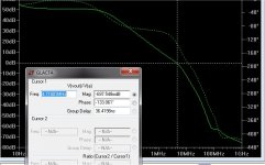
1.2mhz to 1.5 mhz is the VFA upper limit !
These alien CFA's play by different rules.
4.7mhz is where I can get 640V/us(10p). Slight overshoot at this plot.
Absolutely overkill , 47p gives 2.5mhz 250v/us .. this will be the
design target.
PS - Every thing I have ever simulated with KSA992/Ksc1845 - Ksa1381/ksc3503
has almost perfectly been realized in the real build. oscilloscope readings/DMM readings ...
I WOULD NOT waste my time designing a PCB for a "dud" ...
OS
Those devices is not a problem, or any small signal devices for that matter. I can easily get to 10MHz. with those devices.
The real problem lays in the output stage. It is just not fast enough. With an fT of 30 - 40MHz it starts to get a serious problem.
I am trying to find a solution for this at the moment.
I will let you now. Have to dig up some old sims.🙂
To see if it's a CFA just apply the two tests and two pointers!
Main thing that makes a CFA a CFA
Not constant gain bandwidth limited like VFA ie CLG -3 dB BW independent of CLG.
Peak current into the TIS set by the feedback resistor
If you pass THD two tests in favor of a CFA it almost certainly is.
The pointers are
Inv input z is low, non inv hi z
Single gain stage, whereas VFA is always at least 2 ( the reason why CFA 's are easier to comp BTW)
Last edited:
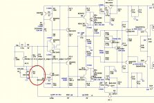
Here's how I got the NX to run with 0-5pf.
The idea came from hawksford's papers.
(below). real simple.
2 more caps .... .68uF works as well .
My feedback question is circled in the attachment , as well.
OS
Nice!
- Home
- Amplifiers
- Solid State
- CFA Topology Audio Amplifiers