Hi Gary,
For the C17 change to X7R 1uF, is the type of the cap or the value or both is the factor of sounding better, just curious.
In 2.6, it was a X7R 0.01 originally, then it was recommended to use the 4.7 tantalum to avoid osciliation. The new value is neither. Hence, my speculative question above, kind of curious it is the lower ESR or lower value or both make it sound better.
Thanks,
Fred,
I made the change because I know that tantalum caps aren't great for high frequency bypassing - ceramic caps are made for just that application. So it's the change in type of capacitor that's important more than the value. I haven't played with different values but I suspect it's not that critical. I used 0.22uf caps in my build and they sound fine and I'm sure 1uf will also be good. I'd guess that anything between 0.01uf to 1uf or more will be good if it's a ceramic cap.
How's your V3 build coming?
---Gary
Hi Gary,
For the C17 change to X7R 1uF, is the type of the cap or the value or both is the factor of sounding better, just curious.
In 2.6, it was a X7R 0.01 originally, then it was recommended to use the 4.7 tantalum to avoid osciliation. The new value is neither. Hence, my speculative question above, kind of curious it is the lower ESR or lower value or both make it sound better.
Thanks,
My bad, C8 was a X7R 1uf in the final V2.6 BOM, the early BOM had 0.01.
Thanks for the quick reply, Gary.Fred,
I made the change because I know that tantalum caps aren't great for high frequency bypassing - ceramic caps are made for just that application. So it's the change in type of capacitor that's important more than the value. I haven't played with different values but I suspect it's not that critical. I used 0.22uf caps in my build and they sound fine and I'm sure 1uf will also be good. I'd guess that anything between 0.01uf to 1uf or more will be good if it's a ceramic cap.
How's your V3 build coming?
---Gary
I finally get a break from work to have some fun 🙂 I hope the Dac will come alive on time to sing Silent Night for me, fingers crossed 🙂
The early BOM had an error. We never used 0.01 µF AFAIK. I used 100 nF with good results.
Gary, I get emails of people that use AC (!) to feed this DAC, emails of people that use 24 V and don't understand why it don't work anymore, emails of people sending pics of nearly baked DACs etc. Luckily I get much much more emails of happy builders. Still, please think of the possible implications of any change of an already good working and sounding device... with so many builders. Builders that sometimes had difficulties to get the DAC going. But better is better, so the change to the original value was made. I just think of a large user base of which I really like to see them all happy and satisfied with their DAC. Also all changes have to be tested by us to be sure. In this case it was you that convinced me to go back to the value/type I originally used on the DAC. In the test phase I spent many hours trying out various caps. At a time one has to make decisions to keep the process going.
BTW not all changes you made will be endorsed by me. For instance using 3.3 µF for C4 (input cap for DC block of SPDIF) which is an improvement with your source. In many cases the source has a DC blocking cap so C4 can even be a short, that is way better than using larger caps. Then why is C4 there ? Because there are devices that have DC at the SPDIF output. Now think of that guy ending up with a broken to not optimal working DAC if we omitted C4, to who will he send his complaints ?
Some changes implicate checking of schematics on an individual basis which is practically impossible. It depends on the experience of the builder to make such changes but we can not make those changes official for we have to adhere to a certain standard. The standard that the DAC needs to work good under various conditions.
For those brave souls who are willing to brave the wrath of JP and try and remove their already installed 4.7uf caps...
Gary
Gary, I get emails of people that use AC (!) to feed this DAC, emails of people that use 24 V and don't understand why it don't work anymore, emails of people sending pics of nearly baked DACs etc. Luckily I get much much more emails of happy builders. Still, please think of the possible implications of any change of an already good working and sounding device... with so many builders. Builders that sometimes had difficulties to get the DAC going. But better is better, so the change to the original value was made. I just think of a large user base of which I really like to see them all happy and satisfied with their DAC. Also all changes have to be tested by us to be sure. In this case it was you that convinced me to go back to the value/type I originally used on the DAC. In the test phase I spent many hours trying out various caps. At a time one has to make decisions to keep the process going.
BTW not all changes you made will be endorsed by me. For instance using 3.3 µF for C4 (input cap for DC block of SPDIF) which is an improvement with your source. In many cases the source has a DC blocking cap so C4 can even be a short, that is way better than using larger caps. Then why is C4 there ? Because there are devices that have DC at the SPDIF output. Now think of that guy ending up with a broken to not optimal working DAC if we omitted C4, to who will he send his complaints ?
Some changes implicate checking of schematics on an individual basis which is practically impossible. It depends on the experience of the builder to make such changes but we can not make those changes official for we have to adhere to a certain standard. The standard that the DAC needs to work good under various conditions.
Last edited:
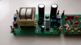
Final finishing touches.
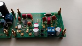
Nice build. If you use longer standoffs for the DAC board you will have less troubles with the too tight DC wiring.
Last edited:
Interesting that you and Subbu tried 100nF (0.1uF). The Abracon XO recommends 0.01uF bypass, datasheet.
Just curious, what made you to decide to go for 100nF and then 1uF?
Thanks,
The Fox also recommends 0.01uF, datasheet:Note: It is recommended
to use an approximately
0.01uF bypass capacitor
between PIN 2 and 4.
So, I thought that was the reason why the early BOM had 0.01uF.Installation should include a 0.01µF bypass capacitor placed between VDD
(Pin 4) and GND (Pin 2) to minimize power supply line noise.
Just curious, what made you to decide to go for 100nF and then 1uF?
Thanks,
Trying out and measuring. Originally I wanted the cap to be between the pins so at the underside of the board but then it would be connected to the pins of the XO only with vias. So I accepted the longer trace and choose a larger value cap. BTW Fox says using 10 nF is to minimize power supply noise but we used a very low noise power supply with a bead to the XO. In this case it is more for the noise that the XO itself generates 😉 Cool that Abracon gives an example how to layout the XO PCB tracks (never saw that one before). I haven't used Abracon XOs myself AFAIK. Many XO's already have an internal small cap for decoupling.
Take the data sheet of ES9023 for example. The given values for many caps are absolute minimum values I found out. Probably because of cost as cost is the factor to take into account in this industry, not quality. So when you build a prototype you will scale up with values and in this case you see an immediate improvement with the Vneg cap for instance which is nice. I recall a guy that shove ES9023 aside as it was not good enough in his opinion buit when he used a larger cap for the Vneg he totally changed his opinion. Some part changes are harder to distinguish though ...
But exactly these discussions are the reason we don't want the schematic published as these matters can take ages and everybody has a (different) opinion on it. Opinions don't build DACs. Before you know it all components will be discussed. Fine with me but I won't participate. I built X prototypes and tested many values for making it possible that people can enjoy 1 good sounding V3 DAC after only a few hours labour.
Last edited:
JP, the schematic and BOM I received are dated August 23 & 22 of this year. Are those the freshest versions available ? I also appreciate your efforts to produce a "wide berth" configuration for we usins entering the DAC world at a more basic level. A third thread centered around tweaking has been mentioned but thought to be unnecessary. Short of that, I'm still planning to collect the essential tips and standards for a stock assembly to be added to the first post in this thread. With more and more successful builds appearing, that could be published in the next few days. I'll PM you the listing for your approval prior to posting.
Last edited:
just to confirm, C7 tantlum capacitor's painted band represents positive side and should be facing L2 due to mistake with board marking ?
Hi All
So C17 must be replaced using X7R 1uF ceramic cap vs tantalum.
May this 1210 package Murata ref GRM32RR71H105KA01K be a good choice ?
I've noticed C7 marking orientation error, maybe it will be usefull to stick it on first post 😉
Regards
Phil
So C17 must be replaced using X7R 1uF ceramic cap vs tantalum.
May this 1210 package Murata ref GRM32RR71H105KA01K be a good choice ?
I've noticed C7 marking orientation error, maybe it will be usefull to stick it on first post 😉
Regards
Phil
......
I've noticed C7 marking orientation error, maybe it will be usefull to stick it on first post 😉
Regards
Phil
It will definitely be included there.....stay tuned😉
I spent all night comparing Subbu dac to Schiit Bitfrost Uber dac and here are my findings:
- Bass : I could not tell if there was any lack of or more bass with Subbu dac
- Soundstage : I felt the soundstage was just a little short, not as wide
- Detail : no glaring differences but on some songs there was a little more detail when played with the other dac but nothing I could point out, both had good detail
- Fatigue : I am very sensitive to digititis and hate bright/harsh sounds so most of my equipment is on the warmer side. Subbu dac confirmed what I been hearing - Schiit was bright, in fact too bright when comparing to Subbu.
There was only one major difference which I never picked up until this comparison - the Schiit played everything (instruments, voices) all at one level - LOUD. With Subbu dac I could hear different levels of loudness creating different layers of soundstage. And this is what I picked up on when first listening, its laid back, probably too laid back for some people. It was interesting that not all instruments were at same level - in some cases I found wanting to turn up the volume on some passages. I am not sure if there is something wrong or maybe something new and I am not use to it ? 🙂 Maybe too much voltage with Schiit... I could easily listen to Subbu all day and dont feel I am robbed of any sound detail or quality.
A $150 project vs $500 Schiit.......well what is my verdict? I really like Subbu dac and to be more fair in comparison I will let it play 24/7 for a week before I do another comparison. But yes its DAMN GOOD !!!!!
Jean-Paul : kolskoot / scot in de roos / bullseye !!!! hole in one 🙂
Last edited:
Thanks Neville. It will become even better (slowly) the first few days. I would not recommend to leave it always powered on but you could do that just for the first few days.
So where is my list, I must cross out Schiit Bifrost (32 bit AKM DAC chip, discrete output stage) 😉
So where is my list, I must cross out Schiit Bifrost (32 bit AKM DAC chip, discrete output stage) 😉
Last edited:
Gary, I get emails of people that use AC (!) to feed this DAC, emails of people that use 24 V and don't understand why it don't work anymore, emails of people sending pics of nearly baked DACs etc. . . . . I just think of a large user base of which I really like to see them all happy and satisfied with their DAC.
JP,
There are many sayings similar to this quote from Douglas Adams - "a common mistake that people make when trying to design something completely foolproof is to underestimate the ingenuity of complete fools."
But I don't think that we're dealing with fools here on DIY, at least not the ones I've met on this thread. We're just seeing many newcomers who are early in their DIY journey. I think it's great that they are jumping in and making mistakes and eventually getting to the finish line with a working DAC. It's even OK that some of them won't ever get it working. That too is part of the learning process. I think we should embrace all these newcomers and help them when they have problems and not try to over-protect them. That's the true fool's errand.
All the best.
---Gary
p.s. for the non-native English readers, a fool's errand is something that has no chance of success.
Guess I understand what you mean and we really do embrace all these newcomers as long as they're experienced enough 😀 but the technical support (we definitely wouldn't give as said before) is practically a one man show. The CEO is very busy with work and he is also got the flue. My job is quite busy as well so ...
If what I am reading between the lines is right you can join in. You are welcome
BTW over-protection is left of the spectrum but stupidity is quite close...
If what I am reading between the lines is right you can join in. You are welcome
BTW over-protection is left of the spectrum but stupidity is quite close...
Last edited:
Phew 😀
Will fire it up on tuesday. Or maybe earlier...
Not the prettiest work out here though but I hope it works !
Fingers crossed
Don't forget the L3-L6 inductors mate. Did you test the regs first?
No, not yet. I ll test reg/then all together with no L's and if values are good - solder L3-6 and plug to the system? Right ?
- Home
- Source & Line
- Digital Line Level
- Build thread - building the Subbu DAC V3 SE