Electrostatic screen in the form of copper foil or thin wounded wire is more often used with toroid than EI or C core transformers , since toroids have high capacitance between primary and secondary. Split bobbin and UI core transformers have very low capacitance and are better for audio.I remember that my transformer manufacturer did not charge extra for electrostatic screen with toroids I had ordered.
Now I am using only low profile UI transformers.
Now I am using only low profile UI transformers.
But is the screen between the Primary/Secondary windings?
Or just a mu-metal or other soft steel band around the circumference of the entire toroid?
If I was to build another phono I would likely use a EI or UI transformer, with screen and encapsulated. I would also use dual bridges as in the Pearl 2.
And then do the most important thing - place the PSU in an unattractive box so you place it out of sight, and a meter or more away from the RIAA amp - guaranteeing that there is no issue from radiated hum! 🙂 🙂
See some Antek toroid models that got both electrostatic and magnetic shields for example. http://www.antekinc.com/pdf/AS-1236.pdf
Transformer electrostatic screen is a copper foil or thin wire between primary and secondary on which usually green/yellow drain wire is soldered. Drain wire is then bolted down on mains safety earth terminal, never on signal earth.
In this way mains noise and transients are reduced, rerouted to mains earth.
In this way mains noise and transients are reduced, rerouted to mains earth.
See some Antek toroid models that got both electrostatic and magnetic shields for example. http://www.antekinc.com/pdf/AS-1236.pdf
Magnetic shield have no drain wire in that transformer. Electrostatic shield drain wire is violet , just like XP-15 transformer.
So the circumference band is not electrically connected? I didn't know that! The internal shield being taken to chassis earth does make more sense...
I learn something everyday. 🙂 This forum is awesome. 😀 😀 😀
I learn something everyday. 🙂 This forum is awesome. 😀 😀 😀
There could be some internal connection to the ground wire for both shields possibly. Else I don't know how it flaps in the breeze and being really effective.
One member using such an Antek reported no hum when in same box with the phono boards in my thread nonetheless.
http://www.diyaudio.com/forums/analogue-source/129126-simplistic-njfet-riaa-1027.html#post3689076
http://www.diyaudio.com/forums/analogue-source/129126-simplistic-njfet-riaa-1032.html#post3693361
Flux band is a copper or brass band around the winding which acts as a shorted turn to the leakage flux only.The band should not be earthed since it may cause unwanted circulating current.
OK then. But I remember hum went best in a tube amp of mine that I dressed its toroid peripherally with a copper band when I grounded it too.
I said it MAY cause circulating currents , eg. if touch mounting bolt etc. You were lucky.
Audio designers , generally do not like comments about their creations.In Pearl 2 pdf document, its designer recommended dual bridge type of power supply(one diode bridge for each polarity).
But in Pass Labs flagship factory made phono stages XP-15 and XP-25, according to high res. photos , they have ordinary single bridge PS !
XP-15 PS it is not even dual mono. Very unusual for the high end phono stages.
Audio designers , generally do not like comments about their creations.
Wayne is the most laid-back and relaxed person -- I'm sure he doesn't care. 🙂 🙂 🙂
In Pearl 2 pdf document, its designer recommended dual bridge type of power supply(one diode bridge for each polarity).
But in Pass Labs flagship factory made phono stages XP-15 and XP-25, according to high res. photos , they have ordinary single bridge PS !
XP-15 PS it is not even dual mono. Very unusual for the high end phono stages.
Without schematics of the current preamps I can only guess why the differences in the power supply but in the Pearl 2 manual Wayne said that he recommends the double bridge rectifier because the Pearl 2 preamp draws more current from the positive rail than the negative. The XP-15 and X-25 are possibly sinking the same current from both rails so two bridge rectifiers wouldn't be necessary.
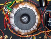
Also, in the picture of the new phono stage I do not see that the violet wire on the transformer primary is connected to ground. I see that it is going to an unterminated pc board land. There appears to be two sets of three primary taps. There are three white jumper wires on the primary side. Two jumpers appear to connect the blue-neutral and brown-hot line wires to the blue and black transformer wires. The third white jumper looks to be connecting the orange and red transformer wires. The transformer appears to have the violet and brown primary wires disconnected. I'm wondering if the picture is of an X-15 for the European market and is set up for 240v with two primary coils connected in series, the red and orange connected. I see the green/yellow safety ground looks to be connected through a power thermistor to signal ground. That is what is done on the Aleph Ono. I see the double three tap power transformer primaries on the Threshold "E" series power amps. They can be configured for 100v, 120v, 220v, or 240v.
From what I have seen in the past an "Electrostatic Shield" in a transformer is between the primary and secondary windings and is connected to ground. An "ElectroMagnetic Shield" is many times Mu-metal to shield magnetic flux leakage and is not connected to ground.
in the Pearl 2 manual Wayne said that he recommends the double bridge rectifier because the Pearl 2 preamp draws more current from the positive rail than the negative.
And dual bridges is the easiest way to control mechanical transformer noise when the dual windings become unevenly loaded.
On the better XP-15 photo, I have seen that violet wire is unconnected.
There is no shield between primary and secondary.
XP-15 input is not complementary, so positive voltage current is higher than negative.
There is no shield between primary and secondary.
XP-15 input is not complementary, so positive voltage current is higher than negative.
Pearl 2 noise
Hi Wellerman,
Over the holidays I had a chance to disassemble, clean, align, (capacitors where needed),etc. my test equipment. Now my Sound Technology has a noise floor of >-102db weighted ANSI. So I put my Pearl 2 back on the bench. Now with the normal gain setting, 5mV In = 1.93V Out as a reference I get -90db weighted. In the high gain setting with 500uV In = 744mV Out as a reference I measure -72db-73db weighted. That is more like I experience in my listening room. Listening again tonight I'm still struck by how dynamic the preamp is and how deep the sound stage is with both a Sumiko Talisman S low Output and a Stanton 981HZS. I know, they are old cartridges but both have low hours and still sound great!
Thanks again to all for the information and inspiration to follow through on this project!!!
Happy Listening All!😀
69/58 does not really look impressive. Would this figure be typical for all Pearl 2's? Mine is a bit noisier (just hiss, no hum) than the built in phono of my Sony TA-FA70es which is spec'ed at 78 (MC)/87(MM) and has higher gain. I think it's the only thing I would like to see improved on the Pearl 2. The sound is great and in practice the noise does not really matter as the groove noise from the record is far higher.
Hi Wellerman,
Over the holidays I had a chance to disassemble, clean, align, (capacitors where needed),etc. my test equipment. Now my Sound Technology has a noise floor of >-102db weighted ANSI. So I put my Pearl 2 back on the bench. Now with the normal gain setting, 5mV In = 1.93V Out as a reference I get -90db weighted. In the high gain setting with 500uV In = 744mV Out as a reference I measure -72db-73db weighted. That is more like I experience in my listening room. Listening again tonight I'm still struck by how dynamic the preamp is and how deep the sound stage is with both a Sumiko Talisman S low Output and a Stanton 981HZS. I know, they are old cartridges but both have low hours and still sound great!
Thanks again to all for the information and inspiration to follow through on this project!!!
Happy Listening All!😀
Those figures are excellent! Especially for the high gain mode. I'm certainly curious how well my unit would score.
Starting Pearl 2 build
I've purchased boards and jfets for the Pearl 2. Other than reading the article a few times and studying a couple of BOM's, that's as far as I've gotten.
Would these two choices make sense:
Using the universal power supply from the diy store.
Using a couple of 2U slimline chassis for the diy store.
I've purchased boards and jfets for the Pearl 2. Other than reading the article a few times and studying a couple of BOM's, that's as far as I've gotten.
Would these two choices make sense:
Using the universal power supply from the diy store.
Using a couple of 2U slimline chassis for the diy store.
- Home
- Amplifiers
- Pass Labs
- Building a Pearl 2