Differential current mirror.
You will need well matched transistors unless you put some R in the Q1, Q2 emitters. Page 146 in Cordell's book has an example for LV with buffering.
Should work well for a LTP splitter stage load too.
You will need well matched transistors unless you put some R in the Q1, Q2 emitters. Page 146 in Cordell's book has an example for LV with buffering.
Should work well for a LTP splitter stage load too.
Last edited:
I dunno much but I understand CCSs can be used on the" top" and "bottom" of a LTP
My experiments with 3 CCS's in an LTP used 6SN7's and was carried out in this thread nearly 5 years ago. I succeded in reinventing the flip-flop. I'm not saying that it can't be done, but I tend to avoid designs that are inherently unstable, especially when designing an amp to be built by someone on the other side of the planet.
http://www.diyaudio.com/forums/tubes-valves/133034-6l6gc-ab2-amp.html?highlight=6l6gc+AB2
The driver board I am using in this design evolved from the design developed in that thread. Overall it is very similar except for the use of pentodes in the second stage. They are needed for a feedback through G2 experiment later. The design seems to work quite well and has succesfully driven two different types of tubes in G1 + G2 mode. I have made 3 identical copies on PC boards, thus I don't see any major design changes in this design.
I am considering pitching the Hammonds for my Sowters on this since you are getting good figures.
I am still using $16 OPT's which are rated for 80VA, about 50 watts. There are three reasons for this. They measure good at 1KHz, even well beyong the rated power, I won't cry if I set one on fire, and I don't want to scratch the shiney blue Edcors.
The final amp that goes in the Landfall Chassis gets the Edcors, and I will hook up the big Plitrons when it's time to break the max audio power record for my lab which is 525 watts on one of Pete's big red boards. My personal max was 1200+ watts back in 1971 with transistors. Exact power was unknown due to my poor measurement capabilities back then.
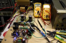
OK, I rewired the output boards to test some little runt sweep tubes. These little guys are smaller than some 6SN7's. They didn't like a 3300 ohm load so I tried 6600 ohms.
They like it.....how well do they like it? Well they didn't break a sweat on 400 volts, so I went to 450 volts. There was no glow at all with all the room lights off, so I let it run for 1 hour. The load resistor was HOTTER than the output tubes! The 8903A read 50 watts at 3.6% distortion. Flipping the output knob on the audio gen up 10 db brings 78 watts at 41%.
So what to do????? You know it, turn it up. 500 volts is no problem either. I let it run at full power for another half hour, 65 watts at 3.14%, 71 watts at clip. +10 db brings screen glow and 98 watts.
These are the smallest tubes that share this pinout. Next up......bigger tubes.
Attachments
My experiments with 3 CCS's in an LTP used 6SN7's and was carried out in this thread nearly 5 years ago. I succeded in reinventing the flip-flop. I'm not saying that it can't be done, but I tend to avoid designs that are inherently unstable, especially when designing an amp to be built by someone on the other side of the planet.
Not the ultimate solution but I got round that by connecting 2.2M resistors in parallel with the (matched) anode load CCS's . Tail CCS adjusted with a multiturn pot . Seems stable , I still run the amp occasionally
316A
I would put my money on 6AU5GT's.....+1 6AU5
You would be right. The type numbers are usually in the file name of the pictures in case I forget to post them.
I only had to move one wire on the output board to test these tubes, so they were the easy choice. Next up the 6AV5GT then the 6AV5GA (not the same tube).
After that, the octal output board will be rewired to test the common pinout audio tubes. I will try the usual suspects, but I am looking for something in the 6V6GT form factor that is good for a 50 watt per channel tube amp that can be stuffed into a 1RU chassis using toroidal transformers.
A 12 pin compactron and a 9 pin novar output board are in the works for testing the big stuff.
PL508/17KW6 should be able to deliver.
I had those tubes running at 25W PD for awhile no problems, no red spots.
Socket is magnoval though, but as you bought lots of sockets for 13GB5 you should have those.
I had those tubes running at 25W PD for awhile no problems, no red spots.
Socket is magnoval though, but as you bought lots of sockets for 13GB5 you should have those.
Socket is magnoval though, but as you bought lots of sockets for 13GB5 you should have those.
I got the sockets......but I ain't got the tubes. I lost my warehouse a little over a year ago, so I moved it ALL into my house.....WIFE =🙁
I have been eliminating my excess stuff for several years because I knew the warehouse deal was ending, and retirement is coming, I have to move everything thats left. I had over 100,000 tubes. Now I have less than 5000. I sold, gave away, or tossed all the oddball stuff and tubes that I didn't have at least 5 of a kind. No KW6's on my list.
I do have several big sweep tubes. The biggest is the LW6. I have them in 6, 26 and 36 volt versions. There are several different constructions. I have seen the big ones run for hours at 75 W dissipation.
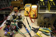
Tonight I revisited some old friends, the 6AV5GA. My first screen drive amp about 6 years ago squeezed 80 watts from these tubes through this OPT on 550 volts. Tonight we test dual drive under the same conditions.
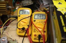
Picture #1....idle current 9mA per tube.
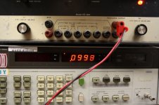
Picture #2....adjust power to 0.1 watt, Ok, 0.0998 watts
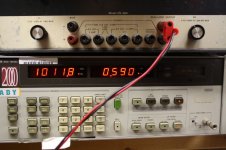
Picture #3....crossover test.......0.590% no problem here.
Picture #4...turn audio generator up till distortion is about 3%
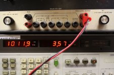
Picture #5....setup 8903 for "watts into 8 ohms"...read meter....117.3 watts.
Picture #6....crank audio gen +10db square wave reads 151 watts, no glow on screen, faint glow on plate. Return to 100 watts, glow goes away.
Experiments over....time for Duck Dynasty
Picture #1....idle current 9mA per tube.
Picture #2....adjust power to 0.1 watt, Ok, 0.0998 watts
Picture #3....crossover test.......0.590% no problem here.
Picture #4...turn audio generator up till distortion is about 3%
Picture #5....setup 8903 for "watts into 8 ohms"...read meter....117.3 watts.
Picture #6....crank audio gen +10db square wave reads 151 watts, no glow on screen, faint glow on plate. Return to 100 watts, glow goes away.
Experiments over....time for Duck Dynasty
Attachments


Tonight we test dual drive under the same conditions.
I forgot to state that the load impedance was 3300 ohms. I went back into the room after watching TV for 1/2 hour. Everything, including the tubes was cold to the touch, except that big gold anodized load resistor it was still rather warm.....Hammond transformer kind of warm. Those things are supposed to be mounted on a thermally conductive panel or heat sink.
faint glow on plate. Return to 100 watts, glow goes away.
That behavior is unusual. Most class AB tube amps dissipate the most power somewhere between 1/3 and 2/3 power. This one clearly got hotter the harder I cranked it. At 150 watts the output was a reasonably clean square wave. I will try to make some more mesurements when I have time.
I don't have many 6AV5's, but I will be rewiring the output sockets for the 6l6GC, EL34, KT88 tubes soon. Then I will melt some more 98 cent 6BQ6's to see if the same failure mode exists as before. I have about 200 of those.
crank audio gen +10db square wave reads 151 watts, no glow on screen, faint glow on plate. Return to 100 watts, glow goes away.
Is the glow going when you turn back to 100W because its no longer a square wave George? I have notived something similar when I was messing about with your 6L6 AB2 design a couple of years ago.
Cheers Matt.
Is the glow going when you turn back to 100W because its no longer a square wave George?
Usually a guitar amp runs cooler when driven to hard saturation. When outputting a square wave the output tubes operate almost like switches alternating between saturation and cutoff, spending little time in the linear region.
The amp shows no color at 100 watts and a very dim redness after a minute or so into extreme overdrive. It should be cooling off. The most logical reason for this would be that the driver is not pushing the output tubes into full saturation. The 6AV5 has a rather insensitive screen grid, so this could be the case, but would require poking around with a scope to prove. I don't have time for this right now.
Usually a guitar amp runs cooler when driven to hard saturation. When outputting a square wave the output tubes operate almost like switches alternating between saturation and cutoff, spending little time in the linear region.
I do wish you'd write a book on tube power amps. You've done some wonderful experiemtents and have great experience with them!
Of course yes, they only spend half the time on and half off with a square wave.
It goes a little deeper than that. True, in hard saturation a tube or transistor switches from hard saturation to cutoff.
When cutoff the tube has plenty of voltage across it (about 2 X the B+) but no current through it (it is cutoff) so the dissipation is zero.
When saturated the current through the tube is at maximum, but the voltage across it is very low (ideally zero) so the disssipation is low.
The voltage drop across a sweep tube can be very low in hard saturation. I have seen levels in the under 20 volt region. The peak currents here should be around 667 mA (550 volts / 825 ohms).
I suspect that the tube is not being fully saturated, leading to higher than expected dissipation under overdriven conditions. I need to hook up the scope and watch the plate and screen voltages, but voltage dividers are needed to avoid blowing the scope input with 1KV+ signals.
I do wish you'd write a book on tube power amps.
As long as I am employed as a full time engineer, I don't have the time, and any publications I write must be approved by my employer, and are technically owned by them. Maybe things will change when I retire (1 to 2 years).
My web site was just rebuilt by another forum member who actually knows how to build a website, so once I learn how to work with it, I will be adding material from my experiments.
As long as I am employed as a full time engineer, I don't have the time, and any publications I write must be approved by my employer, and are technically owned by them. Maybe things will change when I retire (1 to 2 years).
In the meantime, just keep jotting down those notes.
And great website George (I kind of miss the old one now...).
Hi i know this goes back aways. But i have one maybe two 10 amp 10 or 15H chokes from some old UPS equipment. Ill look around my junk box and see whats in there if you want it it's yours but it is huge and heavy and i hate to think what shipping would be.I am looking at a few options. I have some big power iron to use for this amp. One I may have access to is a 640VCT @ 2A power transformer. So, ~425-450VDC B+ @ 2A.
I wish I could locate a choke that is big enough to use for a 2A choke input for ~575VDC, but I cannot locate anything like that. I would love it if someone could assist with finding one for that🙂
- Home
- Amplifiers
- Tubes / Valves
- Show me your screen drive circuits