Milestone: Prototype finished - ready for hearing tests
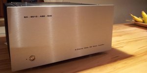
8 months of exiting development are now nearly finished. As a result I can proudly present the first SA2013 prototype for extended hearing tests. A first look:
BR, Toni
8 months of exiting development are now nearly finished. As a result I can proudly present the first SA2013 prototype for extended hearing tests. A first look:
- THD21k@200W@8R is about 3 times higher as the last measured lab example ~ 0.005% (80kHz bw) but
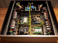
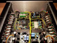
NOTE: prototype has unshielded toroid transformers and all components inside are shielded only by 2 aluminium plates, all cabling inside is unshielded) - Very clear and exact sound. The three-dimensionality is unbelievable good!
BR, Toni
Attachments
Thx all. Don't forget to rate the thread. 😉Yes, exceptionally beautiful 🙂
Make me a custom case 😀
BTW the used chassis are the same as from DIYAUDIO-Chassis. I have bought them directly from the manufacturer in Italy as it is cheaper for us Europeans.
BR, Toni
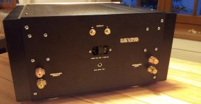
have had time to do CNC milling and engraving front and rear of prototype amplifier...
You did the CNC mill work yourself?
The amp looks excellent in every aspect.
Best wishes
David.
Thank you.You did the CNC mill work yourself?
The amp looks excellent in every aspect.
Best wishes
David.
Yes, CNC milling and engraving is also DIY using my own CNC machine. 😀
Of course with help of my friends (see also the work of diyaudio member Tiroler) which have a very good knowledge on metalworking, milling and engraving. 😉
BR, Toni
Yes, CNC milling and engraving is also DIY using my own CNC machine.
Nice. What machine you have?
I have a turret mill but no CNC yet.
David
Dear David,Nice. What machine you have?
I have a turret mill but no CNC yet.
David
I am using this CNC for milling and engraving: AL640 from HAASE.
Very exact and powerful.
BR, Toni
Toni congratulations on this amazing machine you conceived and executed ! Truly inspiring 😉 as a favor to DIY community if you have time, would be worth documenting your amp so others can feel brave enough to try ! Cheers
Thank you! 🙂Toni congratulations on this amazing machine you conceived and executed ! Truly inspiring 😉 as a favor to DIY community if you have time, would be worth documenting your amp so others can feel brave enough to try ! Cheers
More documentation will follow the next days/weeks depending on my spare time so every skilled DIYer should be able to rebuild this amplifier.
THD21k@200W@8R is about 3 times higher as the last measured lab example ~ 0.005% (80kHz bw) but
NOTE: prototype has unshielded toroid transformers and all components inside are shielded only by 2 aluminium plates, all cabling inside is unshielded)
I am surprised that the distortion increases so much even with what looks to be very careful layout. Shows the importance of details at this level.
Now I am even more committed to divide my amp into two sections and enclose the power supply behind an iron separator, as well as use Faraday screens and iron stray field bands on the toroids.
Best wishes
David.
Dear David,I am surprised that the distortion increases so much even with what looks to be very careful layout. Shows the importance of details at this level.
Now I am even more committed to divide my amp into two sections and enclose the power supply behind an iron separator, as well as use Faraday screens and iron stray field bands on the toroids.
Best wishes
David.
found the source of the higher THD level: output coil. Is it possible that at high frequency (> 10 kHz) and high output levels (~ 40V rms) the output coil is adding distortion? Found no information about output coil distortion. Only output coil crosstalk which is not relevant here.
Putting the thd analyzer probe before output coil shows the very good thd values as from lab prototype.😉
Think there is no need to add iron seperator and faraday screens.
BR, Toni
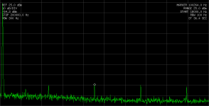
Spectrum before coil (= NFB sense) and after output coil (0.9µH). It seems to be load independent. (Fundamental 20kHz, 40V RMS, THD < 0.002% before coil, THD ~ 0.03% after coil)
Maybe someone has an explanation why we have now more bad harmonics. Is it possible that a wrong dimensioned output coil transports energy from fundamental to higher harmonics? Could we safely remove the coil as we have one zobel on the amplifier board and one zobel directly at speaker sockets on rear panel?
BR, Toni
Attachments

found the source of the higher THD level: output coil. Is it possible that at high frequency (> 10 kHz) and high output levels (~ 40V rms) the output coil is adding distortion? Found no information about output coil distortion. Only output coil crosstalk which is not relevant here.
Putting the thd analyzer probe before output coil shows the very good thd values as from lab prototype.😉
Think there is no need to add iron seperator and faraday screens.
That is another surprise but a step towards the solution.
I plan to screen off the power supply section to reduce hum even with very short, low inductance cables. Faraday screens to minimize any possibility of RFI.
Not really needed but may help.
Best wishes
David
The output coil (Thiele Network) does not need to be beside the amplifier.
Dear David,
found the source of the higher THD level: output coil. Is it possible that at high frequency (> 10 kHz) and high output levels (~ 40V rms) the output coil is adding distortion? Found no information about output coil distortion. Only output coil crosstalk which is not relevant here.
Putting the thd analyzer probe before output coil shows the very good thd values as from lab prototype.😉
Think there is no need to add iron seperator and faraday screens.
BR, Toni
It is better to locate the L//R off the amplifier PCB. I put it in the cable running to the chassis mounted output terminals.
Can you connect the coil remotely with a twisted pair, leaving the R where it is? Then you can move the coils around and find the optimal placement.
The Zobel (R+C) located before the output inductor MUST be at the output of the amplifier.Spectrum before coil (= NFB sense) and after output coil (0.9µH). It seems to be load independent. (Fundamental 20kHz, 40V RMS, THD < 0.002% before coil, THD ~ 0.03% after coil)
Maybe someone has an explanation why we have now more bad harmonics. Is it possible that a wrong dimensioned output coil transports energy from fundamental to higher harmonics? Could we safely remove the coil as we have one zobel on the amplifier board and one zobel directly at speaker sockets on rear panel?
BR, Toni
It MUST be located to minimise the impedance of the route that the output currents take in getting from the Power rails through the Zobel back to the power rail. That makes the location VERY close to the power terminal of the output device and the Power Ground terminal of the HF & MF decoupling.
The more I repeat this bit of advice the more I become convinced that this minimising of the impedance of the Zobel is vitally important to the performance of the amplifier.
Have other Members found evidence that supports my thoughts?
No - but I can shortcircuit the coil and parallel 10R resistor and see what happens between pcb and output connectors.Can you connect the coil remotely with a twisted pair, leaving the R where it is? Then you can move the coils around and find the optimal placement.
BR, Toni
- Home
- Amplifiers
- Solid State
- 2stageEF high performance class AB power amp / 200W8R / 400W4R