Bonsai,
That looks really impressive. Why do you tempt us so? 🙂 Are you planning on offering this as PCBs only, full kit, enclosure, etc? Or, a commercial product through hifisonix.com?
Rick
That looks really impressive. Why do you tempt us so? 🙂 Are you planning on offering this as PCBs only, full kit, enclosure, etc? Or, a commercial product through hifisonix.com?
Rick
Last edited:
this is my project for Class d
http://www.diyaudio.com/forums/class-d/236723-irs2053-irf6665-120w-3ch-class-d-would-you-like.html
http://www.diyaudio.com/forums/class-d/236723-irs2053-irf6665-120w-3ch-class-d-would-you-like.html
Attachments

this is my project for Class d
http://www.diyaudio.com/forums/class-d/236723-irs2053-irf6665-120w-3ch-class-d-would-you-like.html
Nice Plexi!
Regards zeoN_Rider
Bonsai,
That looks really impressive. Why do you tempt us so? 🙂 Are you planning on offering this as PCBs only, full kit, enclosure, etc? Or, a commercial product through hifisonix.com?
Rick
Rick
No I am not going to offer them for sale. I will just put the Gerbers and BOM up when the design is fully debugged and tested.
😎
That is! Bravo Bonsai! Potentiometers (see voltage dividers) from 1.5K and above "infect" the linearity of the following stage.
Have you possibility to try these new LME49990? I ask you because are offered only in SOIC package. I am amazed from their performance!
Congratulations Andrew for your new work! I am sure that you will obtain your target of a so high performance!
Thanks Fotios - any new designs/constructions from your side? Hope things are going ok in your home country.
On my side I find that OPA 1611/12 or the Jfet version 1641/42 to be killer opamps.
Do
Yes, you can experiment with opamps in this design as long as they are single channel DIP.
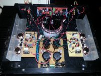
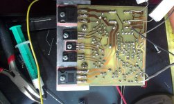
Here's my not so nice looking 150+150W @4 ohms, 2 yr. old integrated amp.😀 but, of course very nice sounding 😉. It's a very simple design, PCB is taken from a 50+50W, 2N3055 amp kit, with some changes to accommodate the upgraded circuit. also there's a 5 band equalizer on it's top.
Regards,
Aniket
Regards,
Aniket
Attachments


Here's my not so nice looking 150+150W @4 ohms, 2 yr. old integrated amp.😀 but, of course very nice sounding 😉. It's a very simple design, PCB is taken from a 50+50W, 2N3055 amp kit, with some changes to accommodate the upgraded circuit. also there's a 5 band equalizer on it's top.
Regards,
Aniket
not look nice? dude that is a beauty do not mind about that you are a pioneer like us searching and designing audio amplifier I call that "audio art" (Audison) 🙂
Regards
Juan
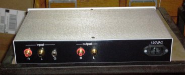
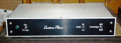
Swetone Phono
This is a project I just finished for someone else. It's a simple phono pre based on the LT1115. The box is from Par-Metal. One thing we did which I've never seen before is to use a trophy shop to make the front and rear artwork & lettering. It was a little tricky drilling through both, but I managed OK. He picked out the design for the panels. Total cost was about $250. I felt honored to be asked to make something for someone else. It's the first time for me. I hope he likes it.
This is a project I just finished for someone else. It's a simple phono pre based on the LT1115. The box is from Par-Metal. One thing we did which I've never seen before is to use a trophy shop to make the front and rear artwork & lettering. It was a little tricky drilling through both, but I managed OK. He picked out the design for the panels. Total cost was about $250. I felt honored to be asked to make something for someone else. It's the first time for me. I hope he likes it.
Attachments
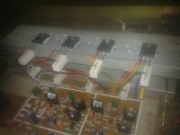
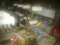
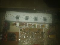
Hi guys, this is still a work in progress.
Its a 5.1 amp system, 5 LM3875T modules for my satellite speakers, and a 250 watt class D module for the subwoofer.
The entire system will soon be controller with an arduino to control speaker protecting, and power saving.
Ampduino!
Ignore that little module in the middle cable tied to the speaker lines, its a temporary 12 volt PSU to get it running for testing.
I still have to mount the power control system, soft start, speaker protection system, and on/off switch.
Oh and snubber caps on the rectifier bridges.
An externally hosted image should be here but it was not working when we last tested it.
An externally hosted image should be here but it was not working when we last tested it.
An externally hosted image should be here but it was not working when we last tested it.
An externally hosted image should be here but it was not working when we last tested it.
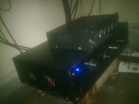
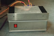
Apex Audio A100 build
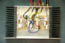
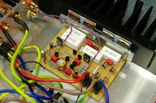
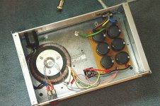
Just wanted to thank Apex for this excellent sounding amp. I put the power supply in a separate enclosure; slightly increased the complexity but worth the effort I think. Please see my photos for details.
Just wanted to thank Apex for this excellent sounding amp. I put the power supply in a separate enclosure; slightly increased the complexity but worth the effort I think. Please see my photos for details.
Attachments
Yellow green is the connection from PE on the IEC socket to the Permanent Chassis bolt.
No other wire should use that colour.
Twisted pairs of Flow & Return.
No other wire should use that colour.
Twisted pairs of Flow & Return.
Just wanted to thank Apex for this excellent sounding amp. I put the power supply in a separate enclosure; slightly increased the complexity but worth the effort I think. Please see my photos for details.
Nice work,
Regards
Yellow green is the connection from PE on the IEC socket to the Permanent Chassis bolt.
No other wire should use that colour.
Twisted pairs of Flow & Return.
Yup, dont use AC wiring colours for your DC stuff, especially dont make Earth anything other then earth.
Other then that a nice layout.
Yellow green is the connection from PE on the IEC socket to the Permanent Chassis bolt.
No other wire should use that colour.
Twisted pairs of Flow & Return.
Noted; I'll make sure my next amp is wired with the correct colours. Thanks for the info.
- Home
- Amplifiers
- Solid State
- Post your Solid State pics here