Let's hope so, Aniket.
But, we cannot know it's all right until you connect the specified power source. Only then can we be sure.
So, let's not open the champagne bottle just yet, a little more patience will not go amiss.
But, we cannot know it's all right until you connect the specified power source. Only then can we be sure.
So, let's not open the champagne bottle just yet, a little more patience will not go amiss.
Let's hope so, Aniket.
But, we cannot know it's all right until you connect the specified power source. Only then can we be sure.
So, let's not open the champagne bottle just yet, a little more patience will not go amiss.
Indeed.
And you really need to revise that input filter too. Increasing C3 is really "fiddling" the issue. You don't need alter the PCB. Just replace the input cap with a cap plus series resistor and change the input filter cap value.
Hello dvv,
i sent you a mail on your id: dvv@beograd.com, but it bounced back.
better you can mail me at aniket.ani_sharma@yahoo.co.in
Regards,
Aniket
i sent you a mail on your id: dvv@beograd.com, but it bounced back.
better you can mail me at aniket.ani_sharma@yahoo.co.in
Regards,
Aniket
Hi,
I'm pleased to hear it's working your amplifier , but I can't see the output coil 😕 ...... or it's a link somewhere on bottom PCB , with wire ?
Regards ,Alex
I'm pleased to hear it's working your amplifier , but I can't see the output coil 😕 ...... or it's a link somewhere on bottom PCB , with wire ?
Regards ,Alex

Hi Aniket . Here is an idea I have tried . Run it through the simulator . The values should be OK to get an idea . The purple node might be best ? I suspect the purple also can have a more even split of values . On the purple version I was able to use 100 R ( 56 + 270 pF on mine ) . The idea is to win back some HF performance whilst maintaining stability .
Here is a Darlington VAS ( etc ) that seems almost too good to be true !
http://www.diyaudio.com/forums/solid-state/74861-single-darlington-line-preamp.html#post856982
Last edited:
Hello dvv,
i sent you a mail on your id: dvv@beograd.com, but it bounced back.
better you can mail me at aniket.ani_sharma@yahoo.co.in
Regards,
Aniket
I may as well say it here and now.
You have all read my whining and moaning about how incomplete DIY projects are, lacking even the most basic protection and amenities. Well, anyone can whine and moan, but the real thing to do is to sit down and do it the way you think it should be done, hopefully achieving excellent results. Even knowing that excellence is most often the result of a long development process.
So that's what I did. Then, when I had a working model in my simulator I was sastisfied with, I asked Alex mm to work his magic. This morning, he came back to me with the first of TWO piggybacked boards, I suspect the big one. It looks like a million dollars.
So, Alex, since I am experiencing unexplained problems with uploading pictures from my PC to this forum, you do the honors. Please post first my PDF schematic, then your current board and when you complete it, the second board as well.
A few points you should know, as you will when you see the schematic.
Quite by chance, my take on this is almost the exact opposite of Aniket's. He opted for what I feel is an atiquated design, from the early 70ies, when it was felt that NFB could solve all problems. My design logic is much more recent, I believe in high local NFB (correct the problem where it begins) and relatively low global NFB. In other words, make it so that it might just work with no global NFB at all, and then use global NFB to polish it up, as an icing on the cake. Off hand, Aniket's global NFB was around 80 dB (10,000:1), mine is just 20 dB (10:1).
This is the result of my understanding that THD, as an absolute value, has NO BEARING WHATSOEVER on the sound, assuming it stays below say 0.3% in the very worst of cases, by which time the amp is dumping over 500W into 2 Ohms.
In other words, the topology which Aniket used was developed to promote specifications at a time of specs wars among manufacturers, while my topology was developed with good sound in mind. Of course, this is certainly not to say Aniket's topology cannot produce a good amp, of course it can, it's just much harder, the odds of achieving that are in my favor (oods, not a guarantee).
Last note: many, if not most, of you will be frightened by the parts count, around 200 bits and pieces. However, understand that as you add this or that subcircuit, the components tend to add up very quickly. And it has regulated power supplies for the input and VAS, protection from overheating and excessive DC, overvoltage and overcurrent, DC offset adujstment taken as much out of the signal path as possible (a completely separate circuit), and full signal status indication, for showing power on, signal present, nominal 0 dB VA (nominal output) point and clipping, all supported by LEDs.
However, you can always leave out any and all of it, except the DC offset circuit, which is simply too useful to be skipped no matter what anyone says, including Nigel. 😀
Last edited:
Hi Dvv , Aniket . DC offset < 100 mV is OK . To be frank I never had it above 40 mV if working correctly . A Rotel RA 931 I fixed recent was an identical 75 mV left and right . I am told some designers do that to reduce crossover distortion ( no idea if true or why ) . A device to detect and protect is great .
My two pole VAS EQ . I suspect 56 + 270 will work for you . The output stage is not the same as the rail or ground . I would imagine it would require more work . I did get very good results especially after 20 kHz when I tried it . I include the rail as I think it was easier to drive in an amp I built ?
For fun I have added a DC offset control to a 741 mic preamp ( it looks like a power amp ) . These days a NE5534 will exceed it in all ways and cost less ( BC560 might have lower noise ) . The BC 560's and current source almost makes a 741 into hi fi . Many recordings that are well respected used this ( 2N4403 's ) . The values in purple are for +/- 40 to 60 V approximately . A friend says some mixing desks still in use have this !
Thanks all,
i would take some time to simulate your mod Nigel.
@dvv, i strongly suggest you to upgrade your simulator to a newer version, the version 12 i use has all the necessary models from ON semiconductor, Texas instruments etc. if not version 12 then upgrade to version 11 atleast. I have used 10.3 version you are using and there's a lot of difference in simulation results of both version for the same schematic. that is why you are getting odd simulation results.
i have one more update, i bought new 2n5551/5401(philips) transistors, and replaced bc546/556 with them. also connected a 1.8K resistor in series after the input cap(2.2uF). did some testing and DC offset now is +8mV and exactly 0mV for channel 1 and 2 respectively. sounds all good.
Regards,
Aniket
@Nigel Pearson
Nige, 100 mV of DC is NOT all right simply because it's so easy to make that number much smaller.
If it does 100 mV of DC with no signal, what might it be doing when dispensing 200 Watts into 4 Ohms?
@Aniket
Many thanks for the tip, Aniket. My version also has some Motorola devices, but is otherwise not too well supplied with models of semiconductors.
I will look into it ASAP.
When I square-wave tested the idea it worked OK . I think it does produce a mild overshoot which I think is acceptable . Sounds good ( more open ) .
I have no experience of amps with DC oftest at 100 mV doing any harm . I will ask around my PA friends to see what they have to say .
I have no experience of amps with DC oftest at 100 mV doing any harm . I will ask around my PA friends to see what they have to say .
When I square-wave tested the idea it worked OK . I think it does produce a mild overshoot which I think is acceptable . Sounds good ( more open ) .
I have no experience of amps with DC oftest at 100 mV doing any harm . I will ask around my PA friends to see what they have to say .
I don't dispute that, Nige, however you should bear in mind that different circuits will behave differently, and some may not be as oblivious as the one you tested.
Also, I imagone that with your amicable temperament, you didn't really think of any vile loads speakers can present. Otherwise well thought of products, like Apogee, Infinity Reference, Yamaha NS1000, AR 3a Improved, that sort of thing.
You know the drill, Nige, as the designer, it's up to you to try to imagine every possible scenario you can think of. There's no telling what can happen.
@dvv
If Lin topology is getting old,
What is your opinion on Apex AX11 topology, simple current mirror allows for push pull Vas instead of CS loaded Vas.
Enjoy your comment as always
Regards
If Lin topology is getting old,
What is your opinion on Apex AX11 topology, simple current mirror allows for push pull Vas instead of CS loaded Vas.
Enjoy your comment as always
Regards
@dvv
If Lin topology is getting old,
What is your opinion on Apex AX11 topology, simple current mirror allows for push pull Vas instead of CS loaded Vas.
Enjoy your comment as always
Regards
What I think you will be able to read below.
An honest question demands an honest answer. Apex technology, I think I know what you refer to, and if I'm right, I use it myself, albeit in a slightly modified form, not quite current mirror, but a derivate of it.
I think that's a good technology, or rather topology, because it does give us a complementry VAS (for inherently lower distortion), but without the noise input of two complementary differential inputs, rather with only one and thus less noise. And it's supremely programmable in terms of performance.
But let me put it this way - a lot of topologies look nice on paper and do well in simulations, but the proof of the pudding is in the way it sounds. Ideally, the amp should disappear, be gone, be non existent, and all you should hear is music. That obviously is the ideal we will probably never attain, but strive towards anyway, and on occasion, get near to. The trick is getting as near to that ideal as we can.
DISCLAIMER: Do NOT attempt to build this amplifier according to shown schematics. This is NOT a final form design, but rather a prototype only, which requires verification in live testing and subsequent adjustment of values.
Let me walk you through it. Most of it is well known, but in the message after this one, I’ll discuss some less well known aspects.
The amp is based on the idea of a heavily LOCALLY degenerated amplifier. This reduces all forms of distortion begore any global NFB is applied, thus making global NFB simply a finishing touch, rather than the cure for all the ills.
The input stage (Q13, Q14) is as plain vanilla differential amp as can be. However, each transistor is biased at 1.4 mA, and the whole stage has a gain of only about 5.5 times (15 dB), which is very low. The combination of these apsects makes the differential pair behave not unlike a FET front end, with very low distortion and a very wide bandwidth. The collector load resistors are just 1.5 kOhms, which makes the output capacitance of the pair realistically unimportant.
Q4 and Q5 change the single ended differential input into a complementary input, thus allowing the VAS to also be complementary, while keeping the input stage noise down to the SE levels.
Q2 and Q6, and Q20 and Q25, are the amp’s fully complementary VAS stage, executed as cascode amps. Their gain is controlled by R5 and R57 respectively into a fixed load, assured by parallel placing of R12 and R44. They also provide for a constant VAS output impedance (more or less). They will be discussed in more detail in the next post.
Q9 and Q15, with associate fixed and variable resistors, act as the bias providing circuit. On the schematic, it is erroniously noted that Q16 is on the heat sink, when it should have been Q15.
Q12 and Q16 are the overvoltage and overcurrent protection devives, as well as their associated parts. Their job is to make sure the amp never gets into trouble because you are asking for too much of voltage and/or current. It’s a single slope design, however, I took a cue from professional gear and included sensors (R96, R95, R16 and R36, R97, R98) for each transistor in the output stagem, rather than the more common in consumer products single sensor for only two transistors. Yes, this would save you the cost of four resistors, and you can still do it that way, but will need to change the value of onty two resistors from 360 to 120 Ohms.
The reason is that I tried to really let the output devices go as far as possible without endangering them. No matter how tight your selection tolerances are, there will still be differences between the transistors, so it stands to reason to check on all of them individually. The added benefit, however small it may be, is that all of the transistors in the output stage are operating under as nearly ideally same conditions as possible.
The output stage is „three deep“, meaning it has a predriver, driver and output stage, three in all. This configuration provides a very high current gain factor, which offloads the VAS from supplying both voltage and relatively high current, is the fastest known connection and provides low distortion and a very small output impedance, which is good for our damping factor (although it has mostly done what it had to do with speaker Q factor by about 20 dB or 10:1). More cannot hurt.
There is no output inductor in parallel with a resistor because I don’t think one will be needed. However, just in case, a separate small output board will allow for it if required by a particularly evil load I haven’t thought of. Even as an afterthought.
Lastly, Q1 and Q26 act as voltage stabilizers. This is just one step above a simple zener diode arrangement, however it does everything it is expected to do. It cannot be compared to a really well done stabilizer circuit, but then it’s much simpler, cheaper and even as such it is literally light years ahead of any arrangement with no regulation that I am aware of. It is also higly flexible, needing only 3V difference between input and output voltages, but capable of accepting way more at the input. They will keep the input stage and VAS at 56.4V or so, comfortably above the current gain stage voltages, and most important, completely irrespective of what’s going on at the output. This should make sure that no matter at what level of loudness you may be playing your music, the sound stage should remain rock solid.
Signal satus display does just that – it uses four LEDS to tell you that the power is on, that there is some signal at the amp input, that you have reached 0 dB VU, i.e. the amp’s nominal power, and that you are soon going into clipping and should immediately reduce volume. It’s 0 dB VU point is adjusted by varying the value of R83. As shown, it will trigger with an output voltage of 28.6 Vrms.
The DC offset circuit is nothing new, they have been made more or less like this for literally decades. Its main virtue is that it is as much out of the audio circuit as it’s possible to do. The easier version would have been to put a say 100 Ohm trimmer between R27 and R28 and to reduce the value of existing resistors to 82 Ohms. But that would put the trimmer squarely into the NFB feedback path, and I didn’t want that.
Lastly, the DC/Overheat protection circuit. This one is not mine, and I have no idea whose is it, it has been circulating around mostly German sites and forums for what seems like forever, at least 15 years. I have seen it used once in an Elektor project (300 Watt Amplifier or some such), dating way back to 1995 or so, but I don’t know if that was the first time it was used. Wahtever, it works reliably and does its job, including a 5 second mute function upon turn on.
The next post will deal with the less usual aspects of this amp.
Attachments
Now for some not so obvious highlights.
The CCS for the cascodes. They appear odd at first glance, but there is a sound (forgive the pun) reason why they are so complicated. Please bear with me.
When we discuss speed in amplifiers, we always look at rise times and voltage slew rates. Somehow, we always forget that while we do need some speed, we also need as much symmtery as we can get, meaning that the difference between rise and fall time should ideally be zero. It can never be zero because of storage effects, but it can be shorter or longer.
Just look at op amps. Their rise times are incredibly short, slew rates enormous, but util recently, their settling times were atrocious, 2,000 nS being quite common. That story began to fade with the appearance of OP275, which cut the settling time down to 200 nS, by a fator of 10. Soon, this went down in op amps like AD 818, 825, 826, 829 etc to just 40 or 50 nS for 1% discrepancy, or 80 and 90 nS for 0.1%. No wonder they offered superior sound. And, thankfully, it caught on, so many modern op amps now have equally short times.
Why is this important? Well, think of it this way: when a say bass sound stops, you do not want your speaker cone vibrating back and forth for a long time before it settles down. This reduces, and sometimes kills dead, ambient or spatial information we crave for. Try a simple test – make a simple headphone amp based on an old school op amp and listen to it. Then change the old school to new school fast op amp, and listent again. For example, for old school use OP37, an excellent sounding op amp, and exchange it for an AD 829 op amp. You can’t fail to hear more space and ambience data.
Assuming all this is so, why isn’t anybody talking about it in discrete audio? Well, some have been talking about it for decades, like Keith Johnson of Spectral, and I happen to agree with him. Also, the fact that say Dan D’Agostino („Mr Krell“) isn’t publically addressing the issue does not mean he’s unaware of it, or that he’s not doing something about it already.
This is where we come in. The sole purpose of diodes D5 and D14 is to reduce the settling or fall time by no less than a factor of 10:1. Their presence makes the cascodes settle down 10 times faster than they would without them, giving us a definitely better sound. I’ve used them for over 20 years now.
The protection circuit. A classic two slope protection circuit. The only difference it offers to some other similar circuits is twofold. The first is that it really lets the output stage transistors rip right up to their true limits, which, by the way, are higher than usual because I use very good, big and heavy heat sinks. This allows me less derating because of heat, and thus makes more power EFFECTIVELY available, so in the end, my initially smaller number of power devices to say Aniket’s amp comes out practically the same, because I use not 150W but 200W devices, so my 3 pairs have the same nominal power capability as Aniket’s 4 pairs. In general, the audio industry sells similar maps with 2 pairs of 150W devices (100W/8 Ohms). I guarantee the slope has been chose so that the amp will push well over 500 Watts into 2 Ohms in peaks.
This neatly brings us to the second aspect. Exactly what is a peak power dissipation? How long should the peak be to be meaningful and not just an advertising gadget? To the best of my knowledge (but I am a little out of touch), only IEC standards clearly state that a peak should last 20 mS. While this may appear to be too short, it does in fact cover reasonably well the leading edges of quite a few transients, but still protects the output stage from burning out from overload.
As shown, my amp is adjusted for a 45 mS pause before activation, or double the IEC standards. However, it has been adjusted to keep the output stage safe at all times, or it loses its meaning. It is possible to readjust it to different time constants, for example for 100 mS, but at the cost of lower current peaks allowed.
When the protection does activate, its operation is not abrupt, but is gradual. If what triggered it changes to a safer value, its operation ceases almost instantly.
If you have strong preconeptions against electronic protection, as unfortunately too many people do, let me say that your are extremely unlikely to ever experience its opration, I reckon 99% of all users never do. But they provide safety beyond any type of fuse known to man, and protect both your amp and your loudspeakers from abnormal operating conditions, and accidental short circuits. I strongly advise you to keep them on.
Lastly, a little trick I picked up from Matti Otala’s initial text on TIM. Look at R7+C12 and R59+C31. They look like Zobel networks, don’t they? And in fact, that’s very nearly what they are. Their job is to remove any residual inductance from the power supply, and in this case, remember you have some pretty big capacitors working down the line.
Because they serve to iron out the capacitors, no ideal vaue for all, as it will depend on hob big are the caps, how many are there, which quality, etc. But I can tell you from experience that the capacitor value will be anything from 220 nF to 680 nF. You can find it yourself by simple switch. At some point, your treble range will open up and attain a level of quality you will find pleasing. Then stop, that’s it.
It will work just as well as a retrofit, I’ve done it a few times, and many others have done it as well. It literally never fails!
Initial preliminary simulation results (may change during development):
Open loop full power bandwidth: 2 ... 78,000 Hz at -3 dB points/8 Ohms
Open loop THD: < 0.3% 20-20,000 Hz, 100W/8 Ohms
Global NFB factor: 20 dB (19.7 dB)
Full power bandwidth, no input filter: 2 ... 340,000 Hz at -3 dB points
Full power bandwidth, with filter: 2 ... 200,000 Hz at -3 dB points
Response: 20 ... 20,000 Hz +/- 0.15 dB at full rated power into 8/4 Ohms
THD, closed loop: less than 0.03%/0.07% into 8/4 Ohms at 28.3 Vrms output 20 ... 20,000 Hz
IM (SMPTE): less than 0.05% for 28.3 Vrms into 8 or 4 Ohms
Voltage Slew Rate with input filter (effective): > 70V/uS
Input sensitivity: < 1.4V p-p into approximately 20 kOhms
S/N ratio: as yet undetermined, hoping for >110 dB „A“ weighted
Exact working schematic is attached. simulation file also.
i had increased base resistors to 2.2R earlier before powering up for the first time.
it was working fine with 1 pair of output transistors, but what's the problem when all 4 pairs are placed??? why it's behaving like this.??
All transistors are placed correctly and are insulated properly.
Confused..
In the end this is the diagram that you used
Exact working schematic is attached. simulation file also.
i had increased base resistors to 2.2R earlier before powering up for the first time.
it was working fine with 1 pair of output transistors, but what's the problem when all 4 pairs are placed??? why it's behaving like this.??
All transistors are placed correctly and are insulated properly.
Confused..
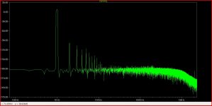
😕 in = 20khz : Confundido:
Hi,
...you have, attached below, all files ,you need ,to made this nice amplifier .😀
Was my pleasure to help again.....
Alex.
They use software alexmm.
What was the final diagram you you based?
Thanks all,
amp works good with more than a few modifications.
1. increased the value of C3 to 100pF from 47pF.
2. increased the base stopper resistors to 10 ohms and driver base stoppers to 47 ohms. all resistors matched.
3. changed the emitter resistors to 3W type. the 5W resistors installed earlier were different in their values, like 1 showing 0.12 and other showing 0.16. so changed them to 0.1R 3W matched resistors.
4. increased the VAS current to 7mA by reducing R6 to 68 ohms.
5. done with the changes.
i had already installed the bias trimmer before even powering up for the first time. a fixed resistor is only shown in the simulation.
connected the amp to the same +/-17V supply i used earlier, without any load and input connected. checked output, shows -2.5mV. fine. checked voltage across 1st emitter resistor, shows 0V(bias trimmer was turned to max resistance). gradually turned trimmer clockwise to tune bias. at about 60 ohms, voltage across 1st emitter resistor is 7.5mV, that equates to 75mA bias current. fine. checked across all emitter resistors on both sides, each shows 7.5mV across them, except one which shows 7.4mV. fine. done with the bias setting. kept the amp on idle for about 30 mins. Checked bias again, it was constant at 75mA per output transistor. all good.
then, connected a speaker and laptop as audio source. good sound again. kept it running loud for 25 mins or so, checked bias again, constant at 75mA.
again connected to the speaker and laptop and listened to some bass songs. bass is really punchy and tight, good control over cone movement.
carried out the same procedure for the other channel also. both the channels working fine now. DC offset is -2.5mV and -8mV for each of the channels.
I am happy😀, amp is working great.
soon i would get the power transformer 40-0-40V15A AC. searching for a good airy chassis.
Regards,
Aniket
¿cual fue el diagrama final que te basaste?
congratulations on finishing it.
- Status
- Not open for further replies.
- Home
- Amplifiers
- Solid State
- Simple 100W power amp