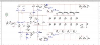
Exact working schematic is attached. simulation file also.
i had increased base resistors to 2.2R earlier before powering up for the first time.
it was working fine with 1 pair of output transistors, but what's the problem when all 4 pairs are placed??? why it's behaving like this.??
All transistors are placed correctly and are insulated properly.
Confused..
What gives you that simulation parameters?
noise:
power:
What was the input signal?
In the end this is the diagram that you used
Hi Sergiods,
the final schematic i am using is attached. the simulation results for the shown schematic are:
330W into 4 ohms 0.009%THD @ 20kHz, input sensitivity 1.97V for 330W. signal noise distortion(SINAD) is 72.6dB.
Regards,
Aniket
Attachments
In the period 1939 - 45 we had engineers who had to get things working . I think you would qualify for what was needed . You now have the luxury of tweaking it if you like . Well done .
My father built radar in the early cold war in Germany . He said in principle what he built was wrong . So wrong as to be impossible . Admittedly what he built was less than perfect . It was perfectly able to work . It was the last period of CH long-wave radar ,this was centimeter radar they were building . My father did not wear uniform nor even shave . It was build radars and nothing else . Later these were replaced . The belief was they had weeks to hold back the Russians . In the end he was hospitalized due to lack of sleep . My dad when I was four taught me electronics . He is 82 now and I teach him electronics .
My father built radar in the early cold war in Germany . He said in principle what he built was wrong . So wrong as to be impossible . Admittedly what he built was less than perfect . It was perfectly able to work . It was the last period of CH long-wave radar ,this was centimeter radar they were building . My father did not wear uniform nor even shave . It was build radars and nothing else . Later these were replaced . The belief was they had weeks to hold back the Russians . In the end he was hospitalized due to lack of sleep . My dad when I was four taught me electronics . He is 82 now and I teach him electronics .
What age was he when he was building radar electronics during the last year of the war?
14?
The Cold war accelerated about 1950 when he was 19 . I seem to remember he said his work was done by 1954 . The advancement of the Jet engine I suspect was the need to plug holes in the radar ?
I sometimes see the back of his head on the History channel . Although not claiming anything it shows wartime use of CH radar . It is probably 1952 just before CH was switched off . My dad says the ladies you just about see are Lord Dowdings daughters . He remembers being asked to do it as they had no wartime film !
I asked my father the other day if he had any reservations about working in Germany seeing as he had almost been killed many times by bombs ( Sutton south London ) . Not at all and he loved working there . He learnt German in 3 months .
One thing which might be relevant . My dad was selected on psychological tests . There were for people who could see aircraft inside noise . Today we have noise averaging to do the same . I often wonder if gifted people do hear things inside feedback loops that the measurements never find . It might even be most of us ?
Chain Home radar station, Rye:: OS grid TQ9623 :: Geograph Britain and Ireland - photograph every grid square!
If anyone is interested ? My mother who is 82 also lived on the farm where it is . He always carried the valves in his pocket when servicing the tower . That way if the radar turned on he would be safe . He did put a notice on the equipment . As dad said better safe than sorry . He is not sure but thinks it was his group who warmed their food using centimetric gear . I suspect it was before them .
They converted the CH to watch tennis in green and grey .
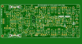
And Alex mm has dne the first part of his magic. Yet to come is the rest, on a separate piggyback board.
Ultimate

Ultimate
Yes, Alex is really good. I can do very well manually, but not as good as Alex.
I haven't checked out the connections yet, waiting for the rest, but it sure looks damn good.
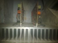
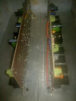
Aniket . I guess you will sell a few ? If so fit heat sinks 4 times larger than you think required is my experience , a slight exaggeration perhaps . Or do what Naim Audio did . Fit an old fashioned bi metal fuse as used on sandwich toasters . A second one to a fan perhaps , a relay will invert the logic ? The beauty of these devices is the are mains voltage rated which reduces the current they will be asked to switch . Like an air bag in a car this is for the worst case . It is possible the amp would need to shift 400 watts of heat if the mains voltage is high and the load below the stated as it often is . Take ambient temperature to be 40 C where you live in the open . Ideally 25 C above that is the limit . 0.06 degree per watt per channel . My feeling is a 0.2 C/W and the precautions might be OK ?
Hi Nigel,
the heat sinks i used are already very big, and would use fan cooling also. you are right ambient temperature here is 40' C, its very hot here.
i would use a separate DC, thermal, short circuit protect soft start circuit on a separate PCB.
Regards,
Aniket
the heat sinks i used are already very big, and would use fan cooling also. you are right ambient temperature here is 40' C, its very hot here.
i would use a separate DC, thermal, short circuit protect soft start circuit on a separate PCB.
Regards,
Aniket
Attachments
I seem to remember a 75 C thermal fuse was used by Naim . Seems a bit high perhaps ?
If you really need to test the amp I have always fancied water cooling . I wondered if TO3 transistors with their heads in the water might work ? It is not ideal as the cooling surface is the other side . If the water is pumped fast enough it might be OK . The head side only needs an O-ring to seal ( machined in if possible ) . The fixing studs held in with waterproof sealant ( Loctite ) . If so the true RMS power can be used . A piece of aluminium rectangular extrusion might be best ? . A car radiator would be cheap . If happy to have it out of sight the car heater and it's fan might be very cheap . My estimate is that a car heater shifts 1000 watts with ease . My best ever result was 120 W rms continuous without a fan . Some say with real music that is 1000 watts . 360 watts realistically . If the fixing stud is nickle plated brass that seems OK .
One thing that is almost a free lunch is using special thermal washers that do not give electrical insulation . The collector sets the heat-sink at rail voltage . If so the heat-sinks are inside the case and on insulated mountings . Remember the rail is equal to ground more or less so offers equal shielding . PNP on one and NPN on another heat sink . Fan cooling is required when in a case . The advantage is that the transistors run slightly cooler all things considered . If taking this route grind the surface flat to get full advantage . You can use glass and grinding paste if saving money . Most stock aluminium will be 95% OK . 10 minutes work to get it perfect . The glass checked with a straight edge . Motorcycle heads also . Metal polish often is good enough as grinding paste .
Nige, are you out of your mind ??????????
You connect your heat sink to act as a rail, I'll just watch what happens when some condensation occurs, or a single drop of a drink during a party falls down on it.
Pros shy away from this, and you're suggesting it to a DIYer?
You connect your heat sink to act as a rail, I'll just watch what happens when some condensation occurs, or a single drop of a drink during a party falls down on it.
Pros shy away from this, and you're suggesting it to a DIYer?
It is usual practice with PA amps . I guess when PA the fact that a health and safety certificate is issued where my friend has to list all risks for his insurance , then the other precautions are minor ?
In all seriousness . If the insulation is OK there will be absolutely no problem . No more so that usual and perhaps less as each heat-sink is separate . Thus only 60 V to ground rather than 120 V local to the output pairs . A glass of beer possibly a little safer than usual ? A good ventilation path would also be a good drainage path . Now you say it this is a real risk either way .
To be frank if well designed with perhaps some type of DIY RCD even a rain storm should be OK . Not ideal . Not to be encouraged . Not 100 % disaster if designed for .
In the UK when valve TV's were common so were flowers in vases . Need I say more !
Last edited:
"Pros shy away from this, "
Crown Powerbase, Powertech, Comtech, Microtech, Macrotech are all made that way, as were many older McIntosh amplifiers.
Crown Powerbase, Powertech, Comtech, Microtech, Macrotech are all made that way, as were many older McIntosh amplifiers.
... all of which are highly professional manufacturers, with stringent manufacturing standards. A wee bit different from DIY folks, I believe ...?
Also, the fact that it can be done, and is in fact being done in some quarters, still does not make it a good idea.
Also, the fact that it can be done, and is in fact being done in some quarters, still does not make it a good idea.
If it is inside a case with a fan it seems if anything to be slightly better from any point of view . The fact the power rail is the heat-sink is only slightly different to water going over the transistor to the heat-sink if water enters the case . In my mind it might be marginally preferable as both are at the same potenial by design when the heat-sink is powered . One slight problem is a piece of metal sent through the cooling holes . If the anodizing is good it should help that , it is said to win more than it looses if black thermally . It can be 100 % OK as an electrical insulator . The big question is forced cooling or not , leading to internal or external heat-sinks . I don't recommend the power to go through the heat-sink . However from a resistance point of view it might be superb ? The proposal is to use PTFE standoffs to the case .
I think these are good questions . From personal experience anything over 100 watts continuous is very difficult .
My friend who does this says the big discussion is 48 V rails . It gets through certification better . We laughed as he says obviously it is 96V in truth . I wonder if having things apart makes the 48 V argument more solid ? If you like mostly it is 48 V to ground and not 96 V across devices .
In my view 2 fans would be good for heat extraction.
1 to pump cold air inside and 2nd to exhaust hot air outside with the first fan directly pumping cold air on the heat sinks.
water cooling is way too complex which includes pipes to circulate water from the sinks to the radiator, and need separate power source. water cooled CPU coolers are available but are still impractical and unsafe for amp cooling as supply rails are high. also transistor mounting would be an issue.
Regards,
Aniket
Agreed . My idea with water is about as simple as I could get it . Have used a water cooled PC , my son had one . I will do a drawing if I get time because it is simple and I doubt any trouble . Having been a mechanical engineer it perhaps seems easy to me . TO 3 is the big deal .
Last edited:
In my view, water cooling is just too much hassle, and besides, while the power you want is rather high, it is still well within reasonable limits and even passive heat sinks alone.
As for a two fan arrangement, one way is what you stated. But getting it right is not very easy. The other way would be to use two fans for exhaust, and putting cover cutouts on the opposite side of them; if the fans are in the back, then the air intake cutouts on the cover should be at the front of the case, so that you make air move along inside from the front to the back. Simplies your work and mounting.
Assuming you use reasonably efficient fans, each moving say 30-36 m3/h, you have a total capacity of 60-72 m3/h. Work out the interior volume of your case, and see how many times it's all exchanged per hour.
Say you have a 3H pro 19" case. Its actual dimensions would be 440(W) x 132(H) x say 360 mm(D) - that gives it a volume of 0.021 m3. Just 60 m3/h, and it's exchanged 1,428 times an hour.
Even Nige should be happy with that. 😀 😀 😀
- Status
- Not open for further replies.
- Home
- Amplifiers
- Solid State
- Simple 100W power amp