euro-format pcb 160 x 100mm:
Nice work, is it tested, can you post schematic? 🙂
Regards
.Nice work, is it tested, can you post schematic? 🙂
Regards
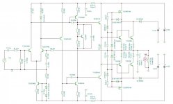
i have checked it visualy for a few times and haven't found any mistakes, if anyone finds some please let me know. the input-voltage stage is done by Dude's layout wich was based on wiljj78's pcb,that part was tested in to3 version only i aded one MPSA transistor as suggested. i believe that Dude will be the first to test it and i'm sure that he will share video,pictures,impresions and some measurments.
.
i am not used to draw schematics,i only draw a few schematics ever but today i will try to in Tina-TI program.
at my mobile i couldn´t but just now at my PC i see a smiley at your post APEX,and let me tell you- No,it will not be made with seven pairs of output and to be put at +/-100 // +/-200Vdc power supply - it stays like this. do some reverse ingeneering to get schematics... 😉 🙂
just kidding 😀
just kidding 😀
Last edited:
at my mobile i couldn´t but just now at my PC i see a smiley at your post APEX,and let me tell you- No,it will not be made with seven pairs of output ant to be put at +/-100Vdc power supply - it stays like this. do some reverse ingeneering to get schematics... 😉 🙂
just kidding 😀
just kidding 😀
at my mobile i couldn´t but just now at my PC i see a smiley at your post APEX,and let me tell you- No,it will not be made with seven pairs of output ant to be put at +/-100Vdc power supply - it stays like this. do some reverse ingeneering to get schematics... 😉 🙂
just kidding 😀
I suggest only one pair of output for AX11 in class H 😉
...and to decrease psu voltage to +20/+30//-30/-20 Vdc,set bias to 3A and put diamond input? 😀 😀 😀
Hi Mile,
What supply voltage do you advice Ax11 Class H with one set of output pairs.
what wattage into 8R,
Thanks again for all you have shared
I have some high SOA MG6333 waiting for a project
http://docs-europe.electrocomponents.com/webdocs/0f92/0900766b80f92433.pdf
What supply voltage do you advice Ax11 Class H with one set of output pairs.
what wattage into 8R,
Thanks again for all you have shared
I have some high SOA MG6333 waiting for a project
http://docs-europe.electrocomponents.com/webdocs/0f92/0900766b80f92433.pdf
Last edited:
sprint layout 5
: Eek:: Eek:: Eek: I has not sprint Layout 6; : Eek:: Eek:: Eek:
Upload in SPRINT LAYOUT 5,Please.
sprint file in ZIP:
: Eek:: Eek:: Eek: I has not sprint Layout 6; : Eek:: Eek:: Eek:
Upload in SPRINT LAYOUT 5,Please.
sprint file in ZIP:
I found the: sprint-layout_6_setup.exe.
but still I can not open the file you uploaded.😕
Sprint Layout 6
This is my sample in full vertions
Regards
maybe your progam still demo vertion,... in full vertions, could be edited with best layout,... thanks... 😉I found the: sprint-layout_6_setup.exe.
but still I can not open the file you uploaded.😕
This is my sample in full vertions
Regards
Attachments

Last edited:
AX 11 Sprint ^6
thanks and regards
thanks for sharing 😉, really helped ease in editing this layout, although this has not been able to build amplifiers, due to limitations of the components in my area.how to do that out of sprint6 version program?
thanks and regards
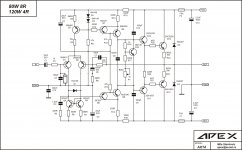
If anyone has drawn out the circuit for AX 11 in class h,
Would you please share the circuit.
Thanks a lot
Would you please share the circuit.
Thanks a lot
If anyone has drawn out the circuit for AX 11 in class h,
Would you please share the circuit.
Thanks a lot
This is very close 🙂
Attachments
H-klasa in pdf (a bit changed...)
maybe this will help:
I found the: sprint-layout_6_setup.exe.
but still I can not open the file you uploaded.😕
maybe this will help:
Attachments
-
AX11 H-klasa bakar toner.pdf63.1 KB · Views: 903
-
AX11 H-klasa bakar foto.pdf63.2 KB · Views: 852
-
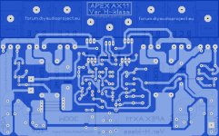
AX11 H-klasa raspored toner.pdf77.7 KB · Views: 888
-
AX11 H-klasa raspored foto.pdf77.8 KB · Views: 801
-
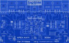 AX11 H-klasa prednjica.JPG585.4 KB · Views: 3,065
 -
 AX11 H-klasa zadnjica.JPG496.3 KB · Views: 2,263
Hello
I have small question, I had some small problem with brumming noise from ax14 amp when input was not connected (prapobly due my board), I have made small change with r2 22k resistor and problem is gone. Now question is if I can leave r2 resistor connected between input and gnd ??
Thanks
I have small question, I had some small problem with brumming noise from ax14 amp when input was not connected (prapobly due my board), I have made small change with r2 22k resistor and problem is gone. Now question is if I can leave r2 resistor connected between input and gnd ??
Thanks
Attachments
Hello
I have small question, I had some small problem with brumming noise from ax14 amp when input was not connected (prapobly due my board), I have made small change with r2 22k resistor and problem is gone. Now question is if I can leave r2 resistor connected between input and gnd ??
Thanks
Yes you can leave r2 resistor connected between input and gnd.
Regards
- Home
- Amplifiers
- Solid State
- 100W Ultimate Fidelity Amplifier