Hi dimkasta,
I use this cable from Shiga to my DAC:
3 foot Apogee Wyde Eye Cable. 75Ω BNC Canare Connectors World Clock GN-WE-BB
http://www.ebay.com/itm/3-foot-Apogee-Wyde-Eye-Cable-75-BNC-Canare-Connectors-World-Clock-GN-WE-BB-/400387013778?pt=LH_DefaultDomain_0&hash=item5d38ecfc92
Regards,
Rudy
Edit: I also removed the BNC from one side from the black belden cable see picture
Attachments
Last edited:
How exactly do you explain this phenomenon?? Please tell!
Well for one, the 75R characteristic impedance cable is important as per the spdif spec.
And in a transmission line, reflections are created when there is a change in impedance. The RCA socket and plug both create significant ones.
Further to that, I am starting to think that wirewound resistors are not appropriate for the attenuator, since their wire is practically acting as part of the transmission line, whatever that means in terms of impedance changes. Not to mention potential inductance causing issues with the square form.
Audio tests in addition to measurements will have to verify or reject this thought though 🙂
Read the start of my post again 🙂
BTW my dac has a BNC connector
dimkasta, so are you running the cable directly from the PCB to the DAC? I thought you cut off one end to replace it with a RCA.
dimkasta, so are you running the cable directly from the PCB to the DAC?
Yep
Attenuator output to DAC's BNC
Hi,Guys can you have a look at that?
It seems to have different mounting holes...
New Genuine Sanyo SF P101 16P Deck Old Version Laser Head Optical Pickup | eBay
Have you gotten your Sanyo laser from
this guy yet? Does it work? Any improvement?
Hi Tibi,
Are you going to do a group buy in the future in connection with a 5 volt super regulator special for V1 V2 V4 V4 ?
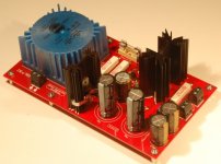
Maybe the simplistic Salas low voltage shunt regulator is a good choise with transformer on the board?
See photo as an example ...
Regards,
Rudy
Are you going to do a group buy in the future in connection with a 5 volt super regulator special for V1 V2 V4 V4 ?
Maybe the simplistic Salas low voltage shunt regulator is a good choise with transformer on the board?
See photo as an example ...
Regards,
Rudy
Attachments
JVC RC-ST3 has arrived. There is inside our famous stuff, our wanted mechanisms in all its glory 🙂 (see #18). What is really good news, and also I like of the board, because of all the parts are whole mounted, no smd-s at all 🙂. There is no onboard digital out, but easyly can soldered a new output.
And what about the JVC RC-ST3? It is using LA9242M and LA6541 chips. But there is a LC78622 DSP chip (with Digital out) instead of LC78601?
Hi Tibi,
Are you going to do a group buy in the future in connection with a 5 volt super regulator special for V1 V2 V4 V4 ?
Maybe the simplistic Salas low voltage shunt regulator is a good choise with transformer on the board?
See photo as an example ...
Regards,
Rudy
SSLV is layout sensitive and any layout other than the BiB has to be very carefully evaluated and measured.
I would stick to BiB and forget about chinese ebay stuff
OK some days it seems that someone is trying to screw up everything you do... like EVERYTHING....
Since the time I woke up today, nothing I do seems to work for some silly reason that renders my entire effort worthless...
And I mean EVERYTHING... And not 2-3 times... like about 20 times since the time I got to work.... The latest one that is relevant here, is that Mouser screwed up the resistors, and instead of 32R4 they sent me 374R...
So the attenuator is worthless... and of course I have no other ~30R resistor... I could try winding one out of res wire, but I m pretty sure that this will get screwed up somehow too...
I m going to sleep 🙁
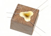
A bit better today.
I made the 14.2dB attenuator using resistance wire and sealed it into wax/wenge. I also used a new technique which should have lower inductance and far less vibration and temperature noise.
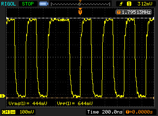
The measurement of the output signal is now spot on, showing an accurate 500mV peak to peak perfect square with nice and fast rise time and no ringing.

Below is the previous measurement with the 12dB attenuator and probably higher inductance resistors.
It's late now to make any audio tests... I ll leave it working for a few hours and audio test it tomorrow.
Anyway, my thoughts are verified... To get the 0.5V output we need a 14.2dB attenuator. Now to see how it sounds...
I made the 14.2dB attenuator using resistance wire and sealed it into wax/wenge. I also used a new technique which should have lower inductance and far less vibration and temperature noise.
The measurement of the output signal is now spot on, showing an accurate 500mV peak to peak perfect square with nice and fast rise time and no ringing.
Below is the previous measurement with the 12dB attenuator and probably higher inductance resistors.
It's late now to make any audio tests... I ll leave it working for a few hours and audio test it tomorrow.
Anyway, my thoughts are verified... To get the 0.5V output we need a 14.2dB attenuator. Now to see how it sounds...
Attachments

dimkasta, that is about as perfect as you can get. Congratulations. You'll have to tell us how it sounds!
I did some listening today before leaving for work. First impression is that music has much much much more power to it. Attack power and speed of drums is amazing, while mids have much bite and energy without losing in detail.
I could easily wrap the transport up now and never think about tweaking it again 🙂
I could easily wrap the transport up now and never think about tweaking it again 🙂
By the way, now that I think of it, the fixed square could also be because of the optimization of the Salas PSU.
That's the trap too many modifications in succession.
It's happen also to me with the elco adjustments to the board and the ALWSR + 5v Built- & Tested Regulator all at once.
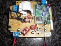
The most beautiful is a second original Vicol Shiga board if there is an improvement with the modified board, then change the original Vicol Shiga board.
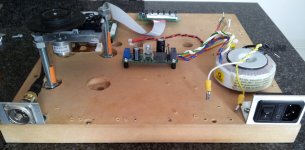
Old pictures, Shiga on the Workbench 😉
Regards,
Rudy
It's happen also to me with the elco adjustments to the board and the ALWSR + 5v Built- & Tested Regulator all at once.
The most beautiful is a second original Vicol Shiga board if there is an improvement with the modified board, then change the original Vicol Shiga board.
Old pictures, Shiga on the Workbench 😉
Regards,
Rudy
Attachments
Last edited:
By the way, now that I think of it, the fixed square could also be because of the optimization of the Salas PSU.
I read through your posts in the Salas thread. Perhaps you could summarize here what you did to both the Salas, and to the Shiga when coupling the Salas to it, to optimize things.
Salas psu is quite versatile and can be quite different with different parts. I used 47uF electrolytic on the Zobel with 0R47 because the pana FR is low ESR, 47uF on the sense lines right on the BiB board and 1000uF electrolytic on the entrance of the psu on the shiga board (V4)
Last edited:
- Home
- Source & Line
- Digital Source
- Finally, an affordable CD Transport: the Shigaclone story