Hi David,
is Dennis Feucht's treatment available somewhere?
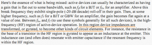
And a probably stupid question, but it is meant honestly: why are you exactly concerned about minimum phase behaviour in this case?
Not sure about Dennis Feucht, but it is widely known that the bipolar Beta has a RHP zero beyond Ft, e.g. http://cktse.eie.polyu.edu.hk/eie304/FrequencyResponse.pdf Then the three legged thing becomes a non-minimum phase system.
... it is widely known that the bipolar Beta has a RHP zero beyond Ft.....
Only if it operated in common emitter mode.
Only if it operated in common emitter mode.
Sure, but it's moot. Beta is defined as the current gain in common emitter configuration.
The most comprehensive example of this, as it pertains to us, is Cherry's Feedback, Sensitivity and Stability of Audio Power Amplifiers. I think you said you had a copy, David.
I have two copies! But I wanted to start with the simplest practical case. An amp with an input admittance y11 and output admittance y22. Feed from a source admittance Ys with a load admittance Yl. And a transadmittance y21.
Then embellish from there. At university I learned all the "eigen this... blah blah" words, as you like to say.
Now days I don't kid myself that I really understand until I can develop an actual example.
I note Cherry scorns my C9 across the VAS emitter 😡 and damns with faint praise Bob's favourite MIC
I noticed that too! If it's as effective as you think then why was Cherry so dismissive?
It is partly the reason why I asked earlier about the impact of C9, I suspected some non-obvious behaviour associated with the low sensitivity to the resistor.
is Dennis Feucht's treatment available somewhere?
Hi Matthias
Start Here.
After you have read the first two parts you may want to track down a copy of his book. I like it, but not sufficiently to sent cash or gold to Belize!
And a probably stupid question, but it is meant honestly: why are you exactly concerned about minimum phase behaviour in this case?
This is not stupid, it is the crucial question!
In your "Nested Feedback" thread I draw attention that Cherry assumes perfect minimum phase behaviour always and infinitely fast VAS/TIS transistors.
If that is the case then it is possible to completely cancel the output transistor poles and extent the gain to infinity.
Of course, with potentially infinite open loop comes arbitrarily low distortion.
So I started to wonder where the scheme breaks down in reality.
Delay and other non-minimum phase is part of the real world limit.
Not sure about Dennis Feucht, but it is widely known that the bipolar Beta has a RHP zero beyond Ft
Only if it operated in common emitter mode.
Sure, but it's moot. Beta is defined as the current gain in common emitter configuration.
Yes, it is clear for a common emitter but not so obvious how it works out in a typical emitter follower output!
It can even be considered that the emitter followers are another nested feedback loop.
Best wishes
David
Last edited:
Hi Waly and David,
thank you for the pointers.

Only beta depends on frequency (but see remark from Dennis Feucht in the text below the schematic). Generator and load impedances are supposed to be known. For the load r_L, this might be realistic, e.g. the usual conductor parallel with resistor, and behind a capacitor of, say, 10nF to ground (assuming an ULGF of 10MHz, the speaker cannot change very much). The generator impedance r_G (driver output) is probably more difficult to estimate, especially without Miller capacitor around the VAS.
If this is the circuit: are we wondering whether G(s)=b(s)/a(s) describes a minimum phase system?
Kind regards,
Matthias
EDIT:
Even if we consider and operate the stage at an ULGF around or larger than Ft, the r_be and c_be changes due to the low-frequency load currents have to be taken into account. So, the analysis would have to be done for different output currents and also voltages (c_cb).
thank you for the pointers.
Is this the circuit we are discussing? (BTW, how does one include such a nice thumbnail that does not need an additonal browser tab?)(quotes from Waly and michaelkiwanuka)
Yes, it is clear for a common emitter but not so obvious how it works out in a typical emitter follower output!
It can even be considered that the emitter followers are another nested feedback loop.
Best wishes
David
Only beta depends on frequency (but see remark from Dennis Feucht in the text below the schematic). Generator and load impedances are supposed to be known. For the load r_L, this might be realistic, e.g. the usual conductor parallel with resistor, and behind a capacitor of, say, 10nF to ground (assuming an ULGF of 10MHz, the speaker cannot change very much). The generator impedance r_G (driver output) is probably more difficult to estimate, especially without Miller capacitor around the VAS.
If this is the circuit: are we wondering whether G(s)=b(s)/a(s) describes a minimum phase system?
Kind regards,
Matthias
EDIT:
Even if we consider and operate the stage at an ULGF around or larger than Ft, the r_be and c_be changes due to the low-frequency load currents have to be taken into account. So, the analysis would have to be done for different output currents and also voltages (c_cb).
Last edited:
I note Cherry scorns my C9 across the VAS emitter 😡 and damns with faint praise Bob's favourite MIC
I didn't think this, David. This is what I found in 'real life.'I noticed that too! If it's as effective as you think then why was Cherry so dismissive?
I'll repeat what I've said twice on this thread already. The value of this sim & theory sh*t is ONLY cos it has some bearing on 'real life'.
Hence the most useful stuff is that backed up by 'real life' examples. I don't agree completely with Gurus Self, Cordell, Cherry & even Great Guru Baxandall cos some of my 'real life' experience jibes with their pet theories. But I certainly don't ignore what they preach. Cos they back their pet theories with 'real life' evidence.
Both Baxandall & Self consider 'pure Cherry' unworkable. Is Prof. Cherry a fraud? Are all Ozzy beach bums unscrupulous liars? 😱
If you allow that both sides are competent, honest and have actually burned solder to test their propositions ... then the only scenario that allows both to be 'right' is that they are doing different things that aren't obvious ... even to these august personages. BTW, GG Baxandall thinks highly of Prof Cherry.
It's winkling out these differences that might increase the store of human knowledge.
As I said at the very start, the main purpose of starting this thread was to persuade Messrs Self & Cordell to at least have another go at 'pure Cherry' rather than dismiss it out of hand.
Then we might have better 'real life' evidence than 20 yr old claims of destitute beach bums 🙂
If I may be bold enough to venture a guess .. I manage without Cherry's evil Ccb 33p at the drivers ... cos I NEVER have drivers & outputs 10cm from the VAS. To me this is TOTALLY evil regardless of TPC, TMC, 'pure Cherry', apples etc.
For C9 across the VAS emitter resistor, there may be another reason for Prof Cherry's scorn. This is a tweak 😱 you do if you eg change outputs. I suspect Cherry likes ALL aspects of his amps to be designed ... leaving no aspect to be tweaked. That's why I usually say 'tweak 😱'
Of course there are many pseudo gurus who appear to be dab hands with SPICE, triple integrals etc but have little or no real life evidence to contribute. These also appear to like [deleted: several pgs of semantic pedantic rant]
My apologies if my totally prejudiced generalisations don't apply to you. 😀
_________________________
Isn't anyone going to tear #4 & #58 apart and explain where I'm cheating with 'pure Cherry'?
_________________________
.. just a reminder that Cherry 1982 shows low sensitivity of audio THD to VAS emitter resistor but high sensitivity of evil oscillation to same.... I suspected some non-obvious behaviour associated with the low sensitivity to the resistor.
_________________________
I think you'll find that Emitter Followers remain Min. Phase even when the transistor has given up. The output is still dragged the same way though less hard.about Min. Phase stuff ...Yes, it is clear for a common emitter but not so obvious how it works out in a typical emitter follower output!
Common emitters stop inverting when they stop working which does nasty things to phase.
A necessary (but insufficient) condition for non-Min Phase is there must be at least 2 separate paths for the signal. Sufficiency is sorta provided if the 2 paths do 'different' things .. especially to phase. In Common Emitters, the 2 paths do different things. In Emitter Followers, the 2 paths sorta do the same thing.
Waly, please pontificate on my wild guess. Not too much 'hard to unnerstan' stuff for us unwashed masses please 😀
PS GG Baxandall sorta mentions this in da Baxandall Papers.
_____________________________
Dave, thanks for Feuchts Part 1. But where is Part 2?After you have read the first two parts you may want to track down a copy of his book.
Hi krglee,I'll repeat what I've said twice on this thread already. The value of this sim & theory sh*t is ONLY cos it has some bearing on 'real life'.
Hence the most useful stuff is that backed up by 'real life' examples. I don't agree completely with Gurus Self, Cordell, Cherry & even Great Guru Baxandall cos some of my 'real life' experience jibes with their pet theories.
nobody can contradict your 'real life evidence'. But as you said, it is backed up by some experience.
So isn't it understandable that others who just see incompatibilities with their own experience and 'standard established theorie' want to understand, before they start smoking transistors and speakers?
[foreigner language question]But I certainly don't ignore what they preach. Cos they back their pet theories with 'real life' evidence.
Do they back up with real life? --> useful theorie
Do they back to real life? --> pet theorie
[/foreigner language question]
Kind regards,
Matthias
Last edited:
Yes, that's what I mean by "think". If you didn't have some evidence then I would say you "believe" it.I didn't think this, David. This is what I found in 'real life.'
Self quits too easily!Both Baxandall & Self consider 'pure Cherry' unworkable.
If the simplistic version is prone to oscillate then compensate the inner loop.
I don't think Cherry is a fraud, but the discrepancies between his experience and other reputable people's mean you can't just say theory is useless and practical results are all that matter.Is Prof. Cherry a fraud? If you allow that both sides are competent, honest and have actually burned solder to test their propositions ... then the only scenario that allows both to be 'right' is that they are doing different things that aren't obvious ...
When the practical results differ then theory is useful to find out why.
I think he only used this as an example of propensity to oscillate, like when you do a lazy test with leads from a power supply. Not as his practice.If I may be bold enough to venture a guess .. I manage without Cherry's evil Ccb 33p at the drivers ... cos I NEVER have drivers & outputs 10cm from the VAS.
Yes, results are the ultimate test. But if someone tells me that they have, say, a perpetual motion machine and that obviously the theory must now be altered to reflect that result then I am inclined to be a bit cautious 😉Of course there are many pseudo gurus who appear to be dab hands with SPICE, triple integrals etc but have little or no real life evidence to contribute.
Yes. I read that but don't yet fully understand it, hence my question... just a reminder that Cherry 1982 shows low sensitivity of audio THD to VAS emitter resistor but high sensitivity of evil oscillation to same.
I would have liked an explanation rather than a reminder.
Very educational for me to work it out for myself😉
I think this is incorrect. For instance a time delay is non minimum phase with only one path. But your view of emitter followers is consistent with Baxandall, Feucht and Matthias, and I am inclined that way too.You'll find that Emitter Followers remain Min. Phase even when the transistor has given up. The output is still dragged the same way though less hard.
Common emitters stop inverting when they stop working which does nasty things to phase.
A necessary (but insufficient) condition for non-Min Phase is there must be at least 2 separate paths for the signal.
Just search the AnalogZone link for the rest of his stuff.Dave, thanks for Feuchts Part 1. But where is Part 2?
Best wishes
David
Last edited:
Hi Matthias[foreigner language question]
Do they back up with real life? --> useful theorie
Do they back to real life? --> pet theorie
[/foreigner language question]
They support their pet theories with evidence from real life.
Still need to think about your other question
Best wishes
David
HF Gyration
Dave Zan in Post # 105 mentioned Dennis L Feucht
I'd never heard of him, so Thanks DZ 🙂 & what a clever guy he is.
In analogZONE Columnist Dennis Feucht: Why Circuits Oscillate Spuriously, Part 1: BJT Circuits Dennis L Feucht discusses & shows examples of HFG, amonst other things
Interesting, & it's noteworthy that a Lot of his references date Way back to the 60's ! So not new info, but "apparently still not well known.
Attachments
Dave Zan in Post # 105 mentioned Dennis L Feucht
I'd never heard of him, so Thanks DZ 🙂 & what a clever guy he is.
In analogZONE Columnist Dennis Feucht: Why Circuits Oscillate Spuriously, Part 1: BJT Circuits Dennis L Feucht discusses & shows examples of HFG, amonst other things
Interesting, & it's noteworthy that a Lot of his references date Way back to the 60's ! So not new info, but "apparently still not well known.
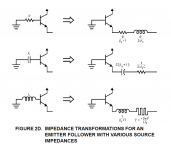
Yes, BJT could transform circuit to another forms due to beta changing with frequency.
Here is the example for Emitter Follower.
PS: The inductance from input will transform to a small inductor plus a "super inductor". The reason call it super inductor is because the impedance is proportion to the square of frequency
Attachments
Last edited:
Self quits too easily!
If the simplistic version is prone to oscillate then compensate the inner loop.
As I have demonstrated, compensating the minor loop with output inclusive compensation requires a relatively large shunt capacitance at the output of the second stage to roll-off second stage gain to unity before the output stage poles take effect.
This capacitor severely degrades the linearity of the second stage as well as the positive slew rate (assuming npn second stage) of the amplifier.
I would stick with TPC as no one here has demonstrated a better way of compensating an amplifier while enhancing loop transmission.
So Douglas Self is essentially right: there is no point dwelling on Cherry's recommendation to include the output stage in the minor loop.
As I have demonstrated, compensating the minor loop with output inclusive compensation requires a relatively large shunt capacitance at the output of the second stage to roll-off second stage gain to unity before the output stage poles take effect.
This capacitor severely degrades the linearity of the second stage as well as the positive slew rate (assuming npn second stage) of the amplifier.
I concur that the shunt capacitor is undesirable.
But your post seems to presuppose that a shunt capacitor is the only option for inner loop compensation.
(To assume for the moment that it is needed at all, as the OP would dispute.)
I have previously proposed what seems a better solution.
Why not nested Miller compensation within the OIC loop?
Should be better for the same reason that simple Miller compensation is better than shunt.
Best wishes
David
Last edited:
I have previously proposed what seems a better solution. Why not nested Miller compensation within the OIC loop?
I have tried it and it seems unstable. Perhaps you could demonstrate a better way?
I have tried it and it seems unstable. Perhaps you could demonstrate a better way?
Not built yet. Still at work on the theory but I should have more to report soon.
To be published in Jan Didden's Linear Audio
Best wishes
David
Nested Miller Compensation?
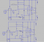
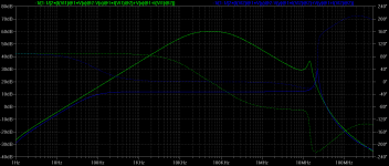
I have run a sim. of two amps with one using simple OIC (green trace, which is unstable) and one in which the 100p Miller capacitor is split into an 80p capacitor around the output stage and a 20p capacitor about the second stage.
The loop gain about the output stage (blue trace) is now negligible and still appears unstable.
Attachments
The loop... still appears unstable.
That needs a bit of a think. I will consider it at the beach, away from the computer!
Best wishes
David
I have run a sim....
Still with two-transistor VAS/TIS and triple output, and still without the VAS/TIS emitter resistor. Even the proponents of OIC seem to agree that your circuits shouldn't work.
Why continue to ignore these points? I don't know whether they will make a difference to your sim results, but it starts to look insincere after a while, and it certainly won't put the issue to bed.
Still with two-transistor VAS/TIS and triple output, and still without the VAS/TIS emitter resistor. Even the proponents of OIC seem to agree that your circuits shouldn't work.
Why continue to ignore these points?
Where did you get the idea that I've ignored those points?

I've pointed out several times in this thread that the TIS emitter resistor makes an insignificant difference to the result.
Moreover, it doesn't make any difference whether a double or triple output stage is used: the OIC loop remains unstable because it's the output transistor poles that are the issue here not those of the drivers.
Similarly, using a single transistor TIS makes no difference: instability is the result of OIC.
So, read my posts in this thread thoroughly and/or do your own sims before spouting nonsense.🙁
- Home
- Amplifiers
- Solid State
- TPC vs TMC vs 'pure Cherry'