If you want to get an idea of what various roundovers and chamfers will do (and driver positioning) then this --> Baffle Diffraction Simulator will do it. Needs excel, and has a bit of a learning curve 😉
Tony.
Tony.
Thanks, it looks to have some interesting info but the interface, yikes...
The programming is acting up somewhat but it looks to be working.
Personally I would have done this in Matlab, much more powerful for numerical calculations.
(I did it for curved surface ESL's so I know it can be done.)
I'll spend some time and see what I can gleem from it. One limitation appears to be driver sizing. There's no way to model 15" drivers...
I have a vague recollection that there is a toggle somewhere that lets you change to larger baffles / drivers... but I could be mistaken 🙂
Tony.
Tony.
Set the piston size and ignore the remaining driver size, it appears to be there just for the illustration.One limitation appears to be driver sizing. There's no way to model 15" drivers...
This sounds as if it's been taken out of context.Geddes is a pioneer and authority in the field. He recommends as large a edge radius as practical.
@ Allen B> Taken out of context most certainly and maybe it didn't come out right?
What I meant to say was that he recommends a large radius edge but he also realize that there are practical limitations on how large you can go. That's about as close as I can get and hopefully I'm not summing it up to badly.
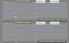
After toying around with the BDS I have this picture to share.
The top half is a sim for sharp edges and the bottom one is 2" round edge.
To me the interesting part is the purple line since it tends to support what I've been saying the whole time. Rounded edges appears to have very little effect on a large driver.
The bluish line is the tweeter and at first glance there looks to be a bigg difference here. Looks can be decieving however. The software is unable to model a compression driver in a waveguide and becomes pretty meningless.
What I meant to say was that he recommends a large radius edge but he also realize that there are practical limitations on how large you can go. That's about as close as I can get and hopefully I'm not summing it up to badly.
After toying around with the BDS I have this picture to share.
The top half is a sim for sharp edges and the bottom one is 2" round edge.
To me the interesting part is the purple line since it tends to support what I've been saying the whole time. Rounded edges appears to have very little effect on a large driver.
The bluish line is the tweeter and at first glance there looks to be a bigg difference here. Looks can be decieving however. The software is unable to model a compression driver in a waveguide and becomes pretty meningless.
Attachments
The bluish line is the tweeter and at first glance there looks to be a bigg difference here. Looks can be decieving however. The software is unable to model a compression driver in a waveguide and becomes pretty meningless.
Yes, it's true, that larger drivers tend to make it less of an issue, assuming a baffle not much larger than the driver diameter. Also, they see less benefit from roundovers or bevels OF A GIVEN SIZE relative to smaller drivers like tweeters, because of the size/wavelength relationship and their inherent HF directivity.
But the changes from the blue tweeter are substantial as shown (and likely understated). Diffraction changes a lot as you move the mic position, making a dramatically less coherent soundfield, and damaging intelligibility and imaging.
A +/- 1dB ripple reduction is quite meaningful to those of us who are pursuing the absolute best we can reasonably attain.
Some diffraction related links from DLR's speaker pages:
Understanding Cabinet Edge Diffraction
Diffraction Doesn't Have to be a Problem
David Ralph's Speaker Pages - Felt Effects on Baffle Diffraction
Re: foam to help with diffraction....It's been my experience that F-13 felt is much more effective, so much so that I've started using it INSIDE the enclosure in place of foam for critical midrange (not midbass) enclosures.
I don't mind perfection. I'm just trying to keep it real, focusing on what really matters and what makes a noticable difference.
I'm not sure a 2" radius will be a great improvement over a 1" radius for example but it'll make a huge difference in the difficulty of building the cabinet.
A rounded edge will probably be much easier to paint than a sharp edge so I'll most likely go for some rounding.
Seeing the big picuture, keeping it real and trying to get the most bang for the buck.
The size of the radius affects the cut-off frequency. Highs are important and the lows, less so. There is some benefit to be had from going a little larger than 2".
The size of the radius affects the cut-off frequency. Highs are important and the lows, less so. There is some benefit to be had from going a little larger than 2".
While I agree that highs are the bigger issue (particularly in normal "narrow" cabinets), wide-baffled speakers need large edge terminations, as the baffle step is lower in frequency and thus needs larger edge termination. Wide baffled speakers tend to do a pretty good job on minimizing HF diffraction regardless of edge termination, due to pathlength losses.
Ok, so the woofer will probably not be an issue regardless of square or radiused edges.
What's your take on waveguides and the Mid to HF frequencies with regard ro cabinet edge diffreaction? The waveguides themselves tend to increase cabinet size to a certain degree.
The whole point of the waveguide is a controlled directivity and it should lessen the illumination of the cabinet edges in a pretty drastic way?
Linkwitz who is a pioneer and authority in himself as well stipulates that rounding the edges will only provide benefits when the radius is greater than 1/8 of the wavelength.
In a document found at Pi speakers you can read about the baffelwidth being a major issue and edge rounding not so much when it comes to lower frequencies.
I'm not sure what to make if it?
A waveguide might for an example exhibit a 90degree radiating pattern at the crossover frequency.
The woofer will probably match the directivity fairly well if done right.
Since the waveguid has such a focused directivity diffraction problems in the higher frequencies should be a non-issue.
When dealing with lower frequencies the wavelengths are so great that the rounding won't do much good anyway.
I'd very much like to hear it from someone who actually understands this stuff.
Please explain it to me in simple terms.
Does edge rounding really do much difference if crossing around 1kHz using a HF driver + CD waveguide and a large DR woofer?
How big does the rounding have to be to make a difference?
I'm just confused from reading to much.
Its not like a waveguides response drops to zero outside of its design angle, there is still radiation that creeps along the baffle and hits the edge. But yes, the radius does not do much for the woofer, but then the wavelengths are very long and it then becomes the whole box that is the diffraction element. Our hearing is most acute at 700 - 5000 Hz and it is this range that diffraction would be most notable and this range where a radius is the most effective.
A spherical enclosure would be nice because it has the lowest possible diffraction, but it is very difficult to make. Practicality is surly something that has to be considered. So the issue, to me, is simply do what you can do in a practical sense and just accept that is the best that you can do.
And for heavens sake don't fixate on the enclosure diffraction only to put the speakers in a location in the room where there are all kinds of diffracting edges nearby. I see that done all the time. A equipment cabinet next to the speaker, or an amp, is just as much of a diffraction object as the cabinet edge. The whole area around the speakers must be diffraction free or all work on the cabinet edges is just wasted.
Thanks for chiming in I was hoping you could shed some light on the subject.
I like it that you make a point about the room variable and nearby objects. I've wondered about how large a difference the details will make and how big a difference it'll make in the end when the speakers are placed in a real livingroom where there's actually living people with real lives.
Since this is DIY I could opt for 2" radius on the edges but it would be much more costly and time consuming plus it would increase the cabinet width.
Is it really worth it or would a 1" radius be just fine? It's quick, cheap and easy to do.
I guess I'm just fishing for a sanity chek?
Only you can answer the question about what is practical. Do the largest radius that you can reasonably do. I can do 1.5" with no more trouble that 1",so I do that. To go to 2" requires special tooling, so I don't do that.
I guess it's about time for me to start sniffing around for some local craft-groups wher I can find a shop and the proper tools.
Thnx
Thnx
G'day marcusA,
For the last few years I have successfully reduced audible cabinet diffraction using BudP's EnABL pattern around the baffle and edges.
The basic principle is that rectangular blocks made of pvc tape create a protrusion on the baffle which interferes with the sound wave travelling along the baffle. Nothing unusual or controversial about that; it's just physics. The interesting thing is that this interference significantly reduces the audibility of diffraction from edges - this is the controversial part You can expect some negative posts dismissing this completely.
Here are a couple of posts describing the effect -
http://www.diyaudio.com/forums/mult...ng-impressions-techniques-20.html#post3384398
http://www.diyaudio.com/forums/mult...ng-impressions-techniques-20.html#post3386849
The block material I use is not paint - pvc duct tape and contact paper (the stuff used for covering shelves) are both effective, along with other similar materials. The pattern size is scaled according to baffle width. There is a calculator in my signature that you can use if you're interested. Happy to answer any questions here or via pm.
Regards,
Alex
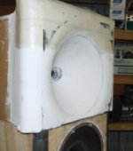
I tried to cinch this issue with a recent build (snapshot taken during construction). I was looking to reduce diffraction back towards the throat from the mouth, hence the size. This is mostly similar to the waveguide it replaces other than this mouth improvement, a change in the throat profile and using better materials.What's your take on waveguides and the Mid to HF frequencies with regard ro cabinet edge diffreaction? The waveguides themselves tend to increase cabinet size to a certain degree.
When measured, there were a few acoustic issues (as one would expect) but they appeared to be simple in nature and low in level.
What I noticed when listening is that this now sounds as if it is crossed over within the passband of the device, in other words it sounds as if it could be crossed lower and that the current crossover frequency is wastefully high. In addition this waveguide manages a good disappearing act.
The crossover frequency is below 1kHz. The outer radius is 2", the waveguide to baffle radius is 4" and the tweeter cab is 25" wide (beside 15" woofer shown, which I no longer use)
Attachments
I'll only make one comment. Do not waste your time with the enabl nonsense, it's about as useless as anything you will ever see. I dismiss it because it is without merit whatsoever with regard to diffraction.I guess it's about time for me to start sniffing around for some local craft-groups wher I can find a shop and the proper tools.
Thnx
Dave
Last edited:
I can't lay my hands on the formwork, but I used two pieces cut from thin plywood to trowel plaster around a wooden substrate. One piece was V shaped for the inner radius and the other was P shaped for the sides. It was simple enough although time consuming as well. As I was only making one pair this didn't concern me.
- Status
- Not open for further replies.
- Home
- Loudspeakers
- Multi-Way
- Speaker cabinets and edge diffraction