yup , that' ZM in da corner
same as on my avatar

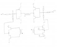
Bravo Zen Mod. Your schematic has several important characteristics:
- The Left and Right amps are mirror images. The schematic has a High Degree of Symmetry.
- The output port of each buffer is a [new] differencing junction.Two signals [In and feedback] are out phase and are added to generate an error signal .
- This error signal drives the gate of the lower JFET, and also the attendant transformer coil.
- The error signal [e.g. from the right buffer] is transmitted to the coil of the upper JFET via transformer action.
better build it
left and right aren't exactly mirror images (drawing itself disregarded) , even if functionally they are , as they must be
left and right aren't exactly mirror images (drawing itself disregarded) , even if functionally they are , as they must be
Read post 3875 quote again. It sums up nicely why i am trying this. Plus, i had to find a wya to annoy ZM until useful information is extracted.
I will, of course, try ZM circuit as well. Legos, legos, on the ground. Legos, legos, all around. In legos, legos much can be found. Legos, legos, can even make a very nice sound.
A great start nonetheless. It is important for the interested DIYers to continue examining your schematic in order to identify potential pitfalls and alert you.better build it
left and right aren't exactly mirror images (drawing itself disregarded) , even if functionally they are , as they must be

A great start nonetheless. It is important for the interested DIYers to continue examining your schematic in order to identify potential pitfalls and alert you.
let them fools ...... let them fools ........

If you look at 1 side of the diff signal, and at the output of that side it is the same phase, you don't have a negative signal for feedback. But, you can feed the other input with that signal because it is opposite phase. And the opposite phase output can be feed back to the 1st input because it is opposit phase. It is certainly easier when driving with a diff amp F.E. but I'm thinking this could be done with the xfrmr configuration. I need to go back a page and read all the stuff since I was here last...flg. you are suggesting to use the power output port of the right-side amp to feedback the left-side amp. And to use the power output port of the left side amp to feedback the right-side amp. Thus the input signal to each buffer and its "bridge" feedback signal are in phase for the purpose of differencing.
And, I think we should remember that susy works best with matched suff. As matched as possible will enhance susy also.
Last edited:


generg. Loved your post. Best regardsthe two little helpers of Zen Mod.....very skilled electronic men....😀😀
gollumgollum
I look forward to your answer.If you look at 1 side of the diff signal, and at the output of that side it is the same phase, you don't have a negative signal for feedback. But, you can feed the other input with that signal because it is opposite phase. And the opposite phase output can be feed back to the 1st input because it is opposit phase. It is certainly easier when driving with a diff amp F.E. but I'm thinking this could be done with the xfrmr configuration. I need to go back a page and read all the stuff since I was here last...
And, I think we should remember that susy works best with matched suff. As matched as possible will enhance susy also.
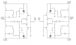
caps are in somewhat wrong positions
disregarding that , good approach
next refinement , please
disregarding that , good approach
next refinement , please
I have been thunking on Dc coupled version. Seem tough, not the caps in signal path is big deal. For 10K pull down, I will need 4-5uF.
this time , level shifters alog with integrated biasing , will became too much complicated;
Vbe multiplier will do , however , flowing through secondary
you'll need some sort of clamping to gnd , to maintain DC offset where it must be
looking at Mithrandir's work , it seems entire complication is not worth price of few Silmics bypassed with proper MKC
Vbe multiplier will do , however , flowing through secondary
you'll need some sort of clamping to gnd , to maintain DC offset where it must be
looking at Mithrandir's work , it seems entire complication is not worth price of few Silmics bypassed with proper MKC
I forgot the question 😕I look forward to your answer.
The dog that I am though...
Attachments
Thanks flg for the schematic. I'll print a paper copy and insert half shaded sine waves to understand its operation. Note that buzzforb and Zen Mod are using only one instead of two Jensens as the principal challenge.I forgot the question 😕
The dog that I am though...
- Home
- Amplifiers
- Pass Labs
- F6 Amplifier