They appear different; despite the blur.FLG, Antoinel,
What difference is there in these two variations?
it is veeery negative feedback ; fact that is "unconventionally" connected back to input is piece of puzzle which is saying that you aren't so keen with toob circs ( feedback from out to input cathode)
funny , nobody said that feedback arrangement is exactly the same as in F5 ?
Funny, nobody said it's exactly the same as tube circuits? Looks like F5 or Current Feedback? I guess I mentioned that but... The semantics of saying it is not negative wrt the input seemed to cover it. It's not an oscilator 😎
I guess you could say I'm not so keen with Hollow State fun. I played with that before I started learning semicunducting theory. I built a little 12AX7/50C5 stereo amp about '73. Maybe when you were riding that Bicycle? There was at least 500 Hollow State devices in my basement before I left for university. My dad since got to old and had his buddys clean out everything my younger brother didn't take for his Harp amps. I have a little collection of (10) 26s, (6) 76s, (2) 45s and I can't remeber what else. I'll get to them sometime. I only have 1 tuby circuit at the moment an Akido with 6CG7/5687. I just like playin with SS more for the moment.
Why is it not negative?
I think I commented on that twice already. It does the function negative feedback achieves but in an uncoventional way by the majority of the circuits seen and discussed here. By feeding back an equivalent phase not 180 degrees different or negative but positive 😱 to counteract the voltage across the primary. What happens if I call it current feedback!
That should stir up some dumbness 🙄
Funny, nobody said it's exactly the same as tube circuits? Looks like F5 or Current Feedback? I guess I mentioned that but.........
Why is it not negative?
well - it is ...... both negative and same as common toob NFB shebang
look at attached F5 circ ; say that sig at Q1 gate is positive ; you are also having positive going voltage at source , voltage sig at drain is negative going , driving gate of Q3 down and opening it ( decreasing it's apparent resistance) , resulting in positive voltage sig at output ;
when you back portion (50/10 of ) of that output signal to same polarity point - source of Q1 , what's happening : gate to source ( input signal ) is , say , 1V - feedback is also upping source for some voltage amount , in same time decreasing action of input signal - better put - decreasing voltage change between gate and source simply lifting source potential , while gate is traveling for 1V up
exactly the same you're having with primary winding in F6 - while input buffer is driving top of primary winding for , say , 1V , nasty bottom of same winding is not staying still at gnd , but is flowing up - driven with feedback net action
so - clearly - feedback action is counteracting input signal ...... so it is negative , which we know it is - by action ...... but it is also , by definition
nasty feedbacksess
gollumgollum
Attachments

Last edited:
I won't argue over this. We apparently see the correct operational theory. Where it goes and what the polarity is are the important criteria to understanding operation. Not what we call it 😀
I think I commented on that twice already. It does the function negative feedback achieves but in an uncoventional way by the majority of the circuits seen and discussed here. By feeding back an equivalent phase not 180 degrees different or negative but positive 😱 to counteract the voltage across the primary. What happens if I call it current feedback!
That should stir up some dumbness 🙄
You are the man and could run mental circles around me. No I am not just saying that. I cant say i understand the circuit, and anything I do understand(used loosely) is a result of bugging the S^$T out of ZM. I am building it on faith😀 it may suck. The fun is in the smoking
 PKI will be down to hear it when its done. Flocchini will get a copy, cause he is F6 junkie
 ZM dont care, just helpin, same as you.
I do like that we kicked up the dust a little in the thread and made our brains, (scratch that, my brain), hurt. Boards arrive Tuesday. Hopefully ill have some measurements soon. Not that I care....if i like how it sounds.
PKI is so behind this brain storming 🙂 stupid academy, just can't catch up without massive reading :-( 🙂
buzzforb. I'll hand-draw your schematic [blurry picture] to see what this fuss is all about.You are the man and could run mental circles around me. No I am not just saying that. I cant say i understand the circuit, and anything I do understand(used loosely) is a result of bugging the S^$T out of ZM. I am building it on faith😀 it may suck. The fun is in the smoking
I do like that we kicked up the dust a little in the thread and made our brains, (scratch that, my brain), hurt. Boards arrive Tuesday. Hopefully ill have some measurements soon. Not that I care....if i like how it sounds.
FLG, Antoinel,
What difference is there in these two variations?
left one (funny mirrored) , I know from before , is good
right one - not enough coffee , probably will work
can't find my thinking hat by day
buzzforb. Do I have your blessing to post the hand-drawn copy of your schematic with an explanation on how it works?Sorry. Its not blurry for me at all. Dont know whats happening.
Sure, although i am not sure i know😀
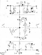
buzzforb. your schematic is attached. I repaired one error in it. It showed the phase [circles] on the Jensens like that in Post #1 by Mr. Pass; which he later corrected. Inspect it for errors. Note the following:
- Top and bottom amps are mirror images; except for the half shaded sine signals which are 180 degrees out phase; as expected.
- The Center Point appears to me as a virtual ground. This enables the top and bottom amps to have a calculated gain like in diyF6
- Suppose that the bottom amp develops a sustained distortion which I depict as a tripod arrow at the positive power output port. For example a buzz absent in the top amp's power output port. This arrow points upward [arbitrary]. Next, follow the journey of this distortion at the points numbered 1 to 6, and note the direction of the arrow [up or down].
- #1 is the power out port.
- #2 is the summing junction at the bottom of the Jensen primary for the bottom amp. Arrow aims upward like the output port.
- #3 is the mirror summing juction for the top amp. The arrow aims up. The resistors bridging points #2 and #3 pass the distortion signal from point #2 to point #3. They talk to each other. Its phase is not changed.
- Transformer action transfers the tripod arrow [distortion signal] to the secondary windings of the Jensen for the top amp; while preserving correct phase as shown at the gates of the R100As [points #4, and 5].
- Note that the arrow at the gate of the top R100A [#5] points downward. It follows that it also points downward at point # 6 which is the source of R100A, and the power output port.
- Note the arrow at the gate of the lower R100A [#4]. It points up. It follows that the bottom R100A inverts the phase of the arrow at its gate, and it shows pointing down at point #6 [drain of R100A] like from the source of the upper R100A.
- This outcome is not preferred. Two bridging amps which operate in an out- of -phase manner [like your amp] afford quadruple the power of either one operating solo. The power output of the buzz is four times that from the bottom amp only. Not good.
- This outcome is remedied by grounding the Center Point. It follows that you have a classical bridge amp whereby the two amps do not talk to each other like the above case; but with 1/4 buzz power output.
Attachments
I hope that flg, Zen Mod, generg, flochinni, and lhquam give their opinions. This amp [as connected] won't go up in smoke; but is expected to have a higher instead of the lower %THD of solo diyF6. Maybe this is beneficial afterall; if this souped-up distortion is the desired type.Told ya i didnt understand.
- Home
- Amplifiers
- Pass Labs
- F6 Amplifier