The plan is to order a lot of different types and give them all s listen. Gotta design adapter board to accommodate them all.The ones I mentioned were just a few examples.
There are/were much more comparable types from other manufacturers.
As e.g. RiFa (PFE-216) in Sweden, Suflex (SUF677, SUF710) in England, Mial in France.
Some switched hat over the years, e.g. the boxed Siemens KS, became S+M KS manufacture (Siemens + Matsushita).
At a later stage, the technology plus the machinery was sold off to EMZ, who manufactured the exact same KS parts with an EMZ logo for a number of years.
What all these types and brands differ in, is not just the technology, but the manufacturing tools.
The German cap winding machinery is/was SOTA, and as you heard from Stuart, tightness of winding the foils (and variations) is half the story.
Not merely the choice of dielectric.
Main and only reason why the boxed Siemens polystyrenes could also be ordered in 0.1% and 0.05% accuracy, straight from the production line (see the link I posted for you).
Difference between a Chevy small block, and one by AMG (with an individual engine computer data file).
Doesn't mean you shouldn't try newer foil cap types, it's the continuous change in technology that makes audio so fascinating.
(and sometimes, a step back can become a step forward)
Ever seen a 0.5uF polystyrene ?
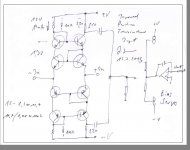
This is the balanced, transimpedance version. That also solves the input offset problem.
Now all falls in place.....
Would you post Foolish Diyer version of SCH so even I can have a go and try please
I am working on a balanced update for the Paradise.
I am planning to put together a kit with everything necessary, including noise screened and selected transistors. I really would like to avoid the trouble we had with Hfe matching and wrong components and delay in the group buy.
The implementation is pretty easy.
The biggest problem is how to setup the servo. We can not use the same method then in the R3 paradise because the biasing is so different.
Yes, the floating current sources allow a bias servo to put in the middle.
I will publish the idea and how i will build the circuit tonight.
I will publish the idea and how i will build the circuit tonight.
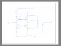
Here is a more elaborate circuit ( scroll down the page ) that is in principle based on the same idea then mine.
You can also see a lot of similarities to the Paradise.
The input is level shifted and combined by mirrors.
ºÍ§Ó*µ响
Nice, I keep this one 🙂
Nice circuit, can be run with floating supplies and with either a mirror out, or simpler with dual capacitors in the output. Not really sure what will be the best performer of the two.. two transistor junctions VS one Cap... something to test...🙂
Sometimes simpler is better. Fact is that DC coupling is the defacto standard.
AC coupling is considered as a compromise. I do not think that way but it is firmly implanted in the brains of many. Brainwash ? Certainly to a degree.
AC coupling is considered as a compromise. I do not think that way but it is firmly implanted in the brains of many. Brainwash ? Certainly to a degree.
Is a capacitor a better current conveyor than two transistors. I believe that would be hard to judge without building and listening to the circuit...
Tankyou Joachim for posting that
I will do my best to work trough it...
Just what I need to move to the other side, or better, inside the box.
I will do my best to work trough it...
Just what I need to move to the other side, or better, inside the box.
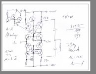
I can not help, i will post an even better circuit where everything is cascoded.
There is still an unnecessary high impedance point between the top transdiodes and the output transistors. That is the beauty ones you understand topology.
That topology can even be improved by earth referenced or floating current sources
Without the current sources the helpers can only drive 1V, no matter how i set the idle.
It is fascinating, like looking into a kaleidoscope.
Michael, it is actually two caps and a resistor.
I would not even say that the caps convey the current. They just block the DC and build a high pass with the resistor. That itself can have benefits to suppress subtonics.
I would not even say that the caps convey the current. They just block the DC and build a high pass with the resistor. That itself can have benefits to suppress subtonics.
Substituting the 220 Ohm resistors with constant current sources would really give us tremendous open loop gain. We then can go the capacitor way or use folded cascodes to sum.
This is totally off topic but nice reading nevertheless. It also contains a primer on how audio came about :
http://www.peavey.com/support/technotes/hartley/chapter_1.pdf
http://www.peavey.com/support/technotes/hartley/chapter_1.pdf