What do you guys think of this, it's a discrete clone of the AD844 with a different buffer, but it looks to me like the distortion rises below 2khz and what is the y axis measurments?
Cheers George
I don't understand why you need to two sets of current mirrors in the IV stage. I tried modeling one similar to this, from the pencil sketch image from a previous post. I don't get good results. THD is too high. It appears that the TZ resistors are loading down the IV stage because the THD went down when the resistor values went up. One thing that could be done is to beef up the IV stage so that it can drive lower resistor values without adding distortion. I don't think the distortion is coming from the diamond buffer, in other words. I also found that DC balance was not that good, but these kinds of amplifiers are known for not having accurate DC response, according to what I have read.
The second mirror set is for the buffer in the AD844... but cascodede mirrors also maintain a higher impedance and thus better distortion specs. for even better you can introduce a helper transistor.
If you want better performance you also need to have CCS's instead of the 3.5 Kohm current set resistors , they modulate the current under signal and will be a primary source of distortion
If you want better performance you also need to have CCS's instead of the 3.5 Kohm current set resistors , they modulate the current under signal and will be a primary source of distortion
Don't know if you guys can understand this, I certainly cannot, but it seems to test test the AD844 quite heavily. If you have some comments please post them.
http://www.emo.org.tr/ekler/ef07f927172f6d4_ek.pdf
Cheers George
http://www.emo.org.tr/ekler/ef07f927172f6d4_ek.pdf
Cheers George
Don't know if you guys can understand this, I certainly cannot, but it seems to test test the AD844 quite heavily. If you have some comments please post them.
http://www.emo.org.tr/ekler/ef07f927172f6d4_ek.pdf
Cheers George
I don't understand all of it, but it's interesting.
Trying to combine the functions of current to voltage conversion as well as low pass filtering with a current feedback amplifier is not an easy thing to do in my mind.
I think this may have been the way Charlie Hansen used multiple AD844's to get his Ayer CDP's I/V stages and LP filtering and buffering all dc coupled as well.
Cheers George
Cheers George
Last edited:
The designer of the AD844 Barrie Gilbert, answer below to letting us see the full schematic of the AD844, he may send them if he finds them. Cheers George
Hi, George.
Regarding the full schematics of the AD844,
I wish I could help, but it has been so many
decades back that I honestly don't expect to
be able to find them.
Barrie
Hi, George.
Regarding the full schematics of the AD844,
I wish I could help, but it has been so many
decades back that I honestly don't expect to
be able to find them.
Barrie
The designer of the AD844 Barrie Gilbert, answer below to letting us see the full schematic of the AD844, he may send them if he finds them. Cheers George
Hi, George.
Regarding the full schematics of the AD844,
I wish I could help, but it has been so many
decades back that I honestly don't expect to
be able to find them.
Barrie
So, it sounds like you are interested in making a discrete version of the AD844, is that right?
Don't know if you guys can understand this, I certainly cannot, but it seems to test test the AD844 quite heavily. If you have some comments please post them.
http://www.emo.org.tr/ekler/ef07f927172f6d4_ek.pdf
Cheers George
I can't seem to link to it now, but I glanced through it before. If I recall: it was an interesting way to create an advanced filter topology using multiple feedbacks, nesting and utilized pin 5 for the gain. It minimized the number of caps (but at the expense of many 844s) and had multiple taps for different freq ranges (3-way xover). It utilized the current feedback of the 844 and had better AC performance (less distortion?) than many regular voltage feedback opamps.
I believe it is just a "regular" opamp filter and not utilizing the unique aspects of the 844 (besides pin 5 for gain) that we are for IV.
So, it sounds like you are interested in making a discrete version of the AD844, is that right?
No just think it would sim better if all the components are put in as well.
Cheers George
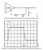
More education if you could guys, looking at the AD844's buffer that can have feedforward around this output buffer from pins 5 to 6 so it can drive high capacitive loads, is it possible to reconfigure the feedforward to become a low pass filter instead of what AD did? Cheers George
" DRIVING LARGE CAPACITIVE LOADS
Capacitive drive capability is 100 pF without an external net-work. With the addition of the network shown in Figure 34, the capacitive drive can be extended to over 10,000 pF, limited by internal power dissipation. With capacitive loads, the output speed becomes a function of the overdriven output current limit. Because this is roughly ±100 mA, under these conditions, the maximum slew rate into a 1000 pF load is ±100 V/μs. Figure 35 shows the transient response of an inverting amplifier (R1 = R2 = 1 kΩ) using the feedforward network shown in Figure 34, driving a load of 1000 pF."
Attachments
Couple of days ago we compared my Cary 303/200 using just the I/V of the AD844, up against the Thorsten Losetch designed AMR CD77 (TDA1541 double crown) that uses Thorsten's special designed I/V stage which I believe is tube based, output impedance <100ohms, so a good match with the Lightspeed as is the Cary. I was expecting the AMR to be better, just by it's reputation and the designer behind it.
3 of us within 20sec thought the Cary was a clear winner, top to bottom, front to back and side to side, and it remained that way for the rest of the session, the owner of the AMR was mute and stone faced and said nothing for the 1.5hrs of A/Bing, and probably saddened by the result, the listening session which went for 4hrs, the last 2.5hrs was the Cary only.
The system was my Lightspeed Attenuator feeding 2 x Halcro DM-78 monoblocks (input impedance 100kohms) pushing a pair of Wilson Watt puppy 8's
This proved what I've been hearing that this AD844 as an I/V is something very very special when used as I've done with no feedback.
Cheers George
So let's get this clear George you're saying PCM1704 with your AD844 beat out Thorsten's TDA1541A with tube stage? If so, I'm perplexed by such a result.
Why so? 844 + 1704 is a good match. 1704 + PMD200 - another good match.
Not to mention both 1704 and PMD200 are in the 5 best DACs/DFs ever made category.
Tubes in I/V is a matter of taste...
Not to mention both 1704 and PMD200 are in the 5 best DACs/DFs ever made category.
Tubes in I/V is a matter of taste...
Well mainly because the TDA1541A is clearly a better DAC technically than the PCM1704 - much lower glitch by virtue of being segmented current source architecture rather than R2R.
what to do with 6ma dac output
hallo ,
any idea ?
my dac gives 6 ma peak output ,to use Ad844 i propose 47 ohm parralled with AD844 input (no feedback).
that means AB844 gets 3 ma.
is that OK or do you have other solutions???
hallo ,
any idea ?
my dac gives 6 ma peak output ,to use Ad844 i propose 47 ohm parralled with AD844 input (no feedback).
that means AB844 gets 3 ma.
is that OK or do you have other solutions???
So let's get this clear George you're saying PCM1704 with your AD844 beat out Thorsten's TDA1541A with tube stage? If so, I'm perplexed by such a result.
Yes I know, I was sure the AMR should have been the better, given it's hype. And I'm not pulling any ones leg here either.
The Cary had far better dynamic swing, far more detail, clearer lower punchier more defined bottom end, more extended transparent high end, a mid range that had more body to it.
We just wanted to keep turning up the volume on the Cary because it never gave any sense getting confused, it's like there was more air around the notes to let you hear what was going on with a blacker back ground. It made the AMR sound like a good old tube amp of yester-year, you know a bit slow a bit thick yet musical still.
Cheers George
Well mainly because the TDA1541A is clearly a better DAC technically than the PCM1704 - much lower glitch by virtue of being segmented current source architecture rather than R2R.
upper 3bits of older ,conventional (not sign magnitude) DAC such as PCM58 or PCM56 etc. were segmented current source .
I think each upper bits of PCM1704's two 23bit DAC have same architecture.
hence their major glitch would be same level.
PCM1704, 63, AD1862 et cetera are in the same league, more or less.
1541 has a bit cleaner switching in theory, yet it has it's flaws in real life - limited oversampling frequency, 16bits and single-chip with common supplies for both channels...
Most of the performance comes from IC's surrounding and their tradeofs management.
1541 has a bit cleaner switching in theory, yet it has it's flaws in real life - limited oversampling frequency, 16bits and single-chip with common supplies for both channels...
Most of the performance comes from IC's surrounding and their tradeofs management.
hallo ,
any idea ?
my dac gives 6 ma peak output ,to use Ad844 i propose 47 ohm parralled with AD844 input (no feedback).
that means AB844 gets 3 ma.
is that OK or do you have other solutions???
That is much more that the PCM1704 so I would just try from the TZ (pin 5) a 1.5k and 1000pf to ground as Pedja did with the TDA1541. And also try the output buffer as is, or something better by comming off the TZ pin to it.
Cheers George
Yes I know, I was sure the AMR should have been the better, given it's hype. And I'm not pulling any ones leg here either.
The Cary had far better dynamic swing, far more detail, clearer lower punchier more defined bottom end, more extended transparent high end, a mid range that had more body to it.
I have an idea that perhaps its incompatibility between the Halcros and the AMR. Halcro from what I know of it is an ultra-low distortion, ultra high-feedback design. The AMR being normal NOS puts out lots of out-of-band images between 22 - 44kHz. Perhaps this ultrasonic output upsets the Halcro and saps the dynamics.
- Home
- Source & Line
- Digital Line Level
- Using the AD844 as an I/V