I am glad Zen Mod does not mind all this fun. Camaraderie by way of thread.You sure it wasn't useless bull sitting on stone pole


What fun? There are pictures on this forum of the Mighty Zen sitting on top of a big stone. We aren't joking! It's all a day in the life of Zen 😀


ZM is frying his sausages. 
I thought that was only for frying sausages?
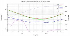
Here is a distortion plot of the F6-Variable-2nd-Harmonic circuit using Fairchild FQA28N15 FETs biased at 1.5A using 0R47 source resistors. The P3-P4 Zen Pots were adjusted to settings as low (toward the source pin of the FETs) as possible, but keeping the 2nd harmonic higher than the 3rd harmonic. The 3rd harmonic is significantly higher than in my Teaser-6 builds using SSR100s.
I have only built one channel and have not yet listened to it.
I have only built one channel and have not yet listened to it.
Attachments
Guys from what I remember from the article, the R100s had minimal thermal drift issues. Is there a need to compensate for it when using IRFs or FQAs?
Guys from what I remember from the article, the R100s had minimal thermal drift issues. Is there a need to compensate for it when using IRFs or FQAs?
Yes, you want a source resistor there, I believe Nelson recommended a minimum of .47R.
The FET's are going to be in the Meg Ohm range, and there is no other path through the secondaries. So it isn't going to bother the transformer, if thats your concern.
It may be useful to have the upper JFET with an adjustable bias and AC coupled to the output, but I don't feel its necessary for operation.
It may be useful to have the upper JFET with an adjustable bias and AC coupled to the output, but I don't feel its necessary for operation.
I think R1,2 and 3 and R1,2 and 3 need to be about 1 ohm not 2 ohm! And, that +23v on the top, needs to be about +60V 😀 Of coarse you will need the appropriately sized sinks...
Otherwise, I like it!
Otherwise, I like it!
Fig,
Can you explain why does the Vcc need to be +60?
In the F3, the extra voltage was there to bias the active load.
Doug
Can you explain why does the Vcc need to be +60?
In the F3, the extra voltage was there to bias the active load.
Doug
More Vcc allows for more output voltage. More Iq allows for more output current 😀
Gain might even increase slightly so you have the option of lowering F.B.
Gain might even increase slightly so you have the option of lowering F.B.
DougL: Please refer to the upper cascode circuit. The idle voltage between the drain and gate of IRFP240 is Vdg ~16 Vdc. Suppose that a positive output signal peaks at 11 V. This transient state leaves a dynamic Vdg ~ 5V; which I am tentatively assuming to be needed for the proper operation of this MOSFET. The expected output power under this proposed condition is ~8 W(rms) into 8 Ohms. I reiterated in other words the response of flg above.Fig,
Can you explain why does the Vcc need to be +60?
In the F3, the extra voltage was there to bias the active load.
Doug
Best regards.
Antoinel,
Thanks for the explanation.
I am going to have to think about this some more. 🙂
Sounds like other topologies are more cascode suitable.
Thanks for the explanation.
I am going to have to think about this some more. 🙂
Sounds like other topologies are more cascode suitable.
DougL, you are welcome. Your schematic is a functional design; noting that nobody complained about its topology. Suppose that the power rails you wish to use are +/-30 Vdc [flg] instead of +/-23 Vdc. The output voltage may then swing 36 Vp-p into an 8 Ohm load for an output power of ~20 W(rms). Please recall what Mr. Pass wrote in his F6 article [and his demo on the scope] that 1 Watt can be fully adequate with a sensistive loudspeaker; maybe of 93 dB SPL.Antoinel,
Thanks for the explanation.
I am going to have to think about this some more. 🙂
Sounds like other topologies are more cascode suitable.
Best regards.
N.B. Will a darlington instead of a MOSFET be suitable? One may be able to getaway with a Vcb ~1.2 Vdc for more output power with lower power rails.
- Home
- Amplifiers
- Pass Labs
- F6 Amplifier