Jac,
Dario Is trying to help with some unexpected voltages on my builds - possibly leakage or some defective parts. This is what I'm getting:
Neg probe to PGND
Pos probe to safety/earth Gnd.
RC Build
Left AC= 45.9V-----Right AC= 27V
Left DC= +200mV --Right = +158mV (these readings keep going up - stoped at 300)
Beta Build
Left AC= 88V ------Right AC = 88V
Left DC= -58mV ----Right DC = -47mV
These are both on boards. Both play music perfectly if correct source is used. I don't think it is a no-metal-chassis problem.
?????????
NOW I UNDERSTAND!
This is a weird suggestion. Try the interconnects and measure the output of whatever is before the amp (pot I am assuming?). If I understand this correctly, the path to ground is the input cable shield. I high resistance or open circuit could leave the amp floating very far away from the safety ground.
Dario should comment first on whether this is a good idea, but I might try a fused connection between the input shield and safety ground. I'm guessing this is almost the same as connecting PGND and will introduce hum, but if it blows the fuse, then it suggests more power than "floating".
Man, I hope you figure this out.
Jac
Just for clarification, I do not have any hum and I have the FEs mounted on a wooden board. That means, no connection between safety ground and PGND.
Fine 🙂
But it was still interesting to measure, so...... with the amps on and connected to the DAC + bare pot, I measured 0.4 mV DC, then switched to the AC channel and measured about 10.4 mV AC. This was the same for both channels and stayed the same with music playing or not.
I've similar readings.
so connecting PGND to safety earth might be expected to generate a hum.
Mmh, actually it's not so...
If we don't connect the FE amp to safety ground, but the chassis is properly grounded, then safety should be served as long as the box stays closed. I'm not sure this is true with Class 1 transformers. I need a better understanding.
I do agree but I'm not an expert here.
It looks like the FE and other MyRefs refer to ground through the shield of the input signal via R11, so the DAC or other source provides the reference to ground. That assumes isolated single end connectors at the chassis.
Exactly
If you follow Andrew's suggestion, then the input shield connects to chassis ground and, if you have a high quality star ground near that point for the safety ground, then you should minimize the hum risk and reference earth within the amp. This approach is recommended by Douglas Self. In neither case would PGND be connected, although it might be interesting to see what happens if you ran a wire from PGND to the star ground.
I'm not sure this is what Andrew said...
From what I know input shield connected to chassis (and chassis to safety earth) would imply a jumper in place of R11...
As I say above, I am just trying to better understand what is happening so that I can build a boxed version that stays quiet for hum.
For my brother build (and when I'll finally assemble mine) I've used a simple grounding scheme:
chassis to safety earth, input shield insulated from chasssi, PGND left floating.
When I'll have my chassis ready I'll try to connect PGND to safety earth via a ground breaker.
Dario should comment first on whether this is a good idea, but I might try a fused connection between the input shield and safety ground. I'm guessing this is almost the same as connecting PGND and will introduce hum, but if it blows the fuse, then it suggests more power than "floating".
I don't know for sure but it sound potentially dangerous to me...
I would focus my attention to transformers wiring...
I don't know for sure but it sound potentially dangerous to me...
I would focus my attention to transformers wiring...
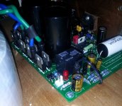
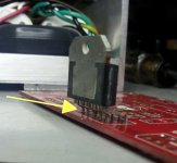
Last week I took the risk and reversed the power leads on one board. They normally are as in the photo - Green closest to M-Caps. Made no difference on hum and amp worked correctly.
Just now checked transformer while not connected to amp - 27.1 & 27.2.
I did blow a non-slow-blo 3 Amp fuse at first attempt at this, so I'm going to remove the transformers and check for internal short/leakage in each one. These are the Antek 300VA with extra shield. I did power the RCs with the ApexJr 120 VA toroids last week when I removed the sockets. Hum was still there.
Sunday I reheated everything except the heat sensitive pieces.
If anyone other than Dario, Jac and me has access to the measurements as shown above, please read and post when it's convienient.
Thanks All
Attachments
Don't laugh - I'm just learning 😡
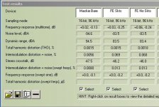
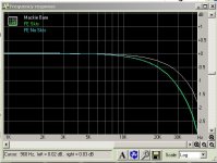
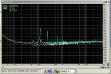
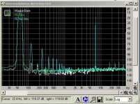
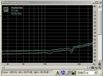
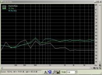
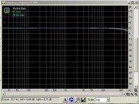
My first attempt to use some diagnostic software - RMAA -with the MyRefs. I settled on a firewire Mackie Sarellite with high quality ONYX preamp section. It was the quietest of several tested. I don't know how helpful this is cause as I read the charts - I should put the sockets back in 😕
Just used one channel and adjusted to 2.3 db on all tests. The Visual Analyzer is much more sophisticated but has a high learning curve and no English documentation. Here is a link to a tutorial if anyone is interested. The thread here is mostly inactive but I'm pushing -as usual.🙄 When I learn what I'm doing VA should be able to show a lot of voltage and scope info.
Not a lot of great or useful information here but - "Every Journey Starts With The First Step" 😉
Edit: These were performed on the beta builds.
Attachments
Last edited:
Guys, it hapened second time to me to go for a speaker listening with my MYREF and to trigger SPIKE (i suppose).
First time happened with Spendor SA1 and now with XTZ 99.25MKII.
Things are the following: when i play to high sound levels but not so high i can hear some cracks in the tweeters. If i decrease a little bit (3db) sound level from preamp this cracks are gone.
Spike is about limiting voltage/current on output or is about chip temperature?
Should i decrease a little bit the transformers voltages?
I'm running 2 toroids 2x24v, 250VA.
Heat Sink A4291-60 :: Heat Sinks :: Electromechanical :: Electronic Parts :: Banzai Music
I can post a picture from my amplifier tomorrow.
The sink does not become very hot after even long listening sessions, this happens with rather insesitive or power hungry speakers and from here i conlude is not related to heatsinking.
I can post a picture from my amplifier tomorrow.
The sink does not become very hot after even long listening sessions, this happens with rather insesitive or power hungry speakers and from here i conlude is not related to heatsinking.
Last edited:
That looks big enough. Did you use good thermal paste on the chip? You should also check that the LM3886 is truly flat against the heat sink. If the chip touches the board a gap can exist near the bottom. This is the FE, correct?
OK, Dario provided a little space to prevent the chip from touching, so if you mounted them correctly (small gap under chip) there shouldn't be interference. Double check the tightness of the LM3886 mounting bolt/nut also.
I have 27 VAC from the 300 VA toroids so yours would appear to be in spec.
I have 27 VAC from the 300 VA toroids so yours would appear to be in spec.
Attachments
I've checked this aspect and is ok. As i never heard how SPIKE behaves i don't know if my problem is related to Spike protection.
I've checked this aspect and is ok. As i never heard how SPIKE behaves i don't know if my problem is related to Spike protection.
atupi,
I don't have any personal experience with Spike, but maybe this from the datasheet would help.
"SPiKe protection means that these
parts are completely safeguarded at the output against ov-
ervoltage, undervoltage, overloads, including shorts to the
supplies, thermal runaway, and instantaneous temperature
peaks. "
Just checking, are you using 4 ohm speakers? Others have found that 24 V transformers have too much voltage for 4 ohm speakers and recommend 22 V. I have 4 ohm speakers with a 3 ohm minimum impedance and 22 V transformers. I haven't gotten to full volume, but I play pretty loud and don't have any issues.
I also remember reading a FAQ answer on Twisted Pear where they suggest that the LM3886 has a current limit of about 11 amps. In that case, they were using 2 LM3886 bridged to provide twice the voltage, but were still finding a limit in current.
Jac
Early Morning, Bob?
What were you doing up at 3 am?
Anyway, I made another measurement, just out of curiosity. I disconnected the input and shorted it with a clip lead. With the amp turned on, the voltage between safety ground and PGND was:
0.04 mV DC (floating around and at the limit of my VOM)
1.1 V AC
I thought the voltage would be higher since the ground reference through input was disconnected, but the voltage only went up a little in AC.
I wish I knew how this explained your 88 V, but I don't.
Jac
Saw a PBS special where they said Einstein and Edison worked four hours and slept four hours. Thought I'd try it to increase my brain power. So far the only result is dark circles, puffy eyes and a headache.
Guess I'm stuck with RTFM.😀
Guess I'm stuck with RTFM.😀
Hi,
Today I tried to measure values to fix one of the broken channel.
C102 = 1.86 [Floating]
C202 = 14.46
Audio is coming from both the channels. But DC offset to the faulty board is >3v. Any suggestions?
Thanks
Badri
Today I tried to measure values to fix one of the broken channel.
C102 = 1.86 [Floating]
C202 = 14.46
Audio is coming from both the channels. But DC offset to the faulty board is >3v. Any suggestions?
Thanks
Badri
Today I tried to measure values to fix one of the broken channel.
C102 = 1.86 [Floating]
C202 = 14.46
Audio is coming from both the channels. But DC offset to the faulty board is >3v. Any suggestions?
that's the problem... C102 should measure +14.6VDC and C202 -14.6VDC
Take other measures and post them:
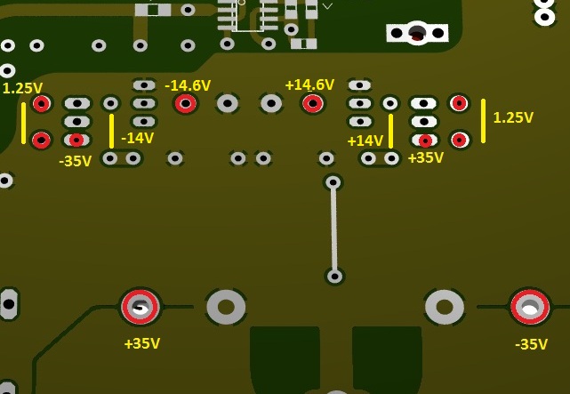
that's the problem... C102 should measure +14.6VDC and C202 -14.6VDC
Take other measures and post them:
I think i have shorted transistors and the regulator. What if the defined values are not getting? Do I need to change this components?
I think i have shorted transistors and the regulator. What if the defined values are not getting? Do I need to change this components?
Yes, probably only the transistor but to be absolutely sure I'd change also the LM317
- Status
- Not open for further replies.
- Home
- Amplifiers
- Chip Amps
- My_Ref Fremen Edition RC - Build thread