Unfortunately, diy F6 is unfinished business. I have a stash of 4 R100As and that is no consolation; R100A appear to be obsoleteium . DIY F6 has no spare parts;and there is not a clear solution for its new output stage.
well - if you have two pairs of Semisouths , it is finished business for you
and , if made properly - it will outlives you , for sure
I also have a stash of 4 x R100s, 2 of which were originally lined up to upgrade my F2, but that was a long time ago and the urge has passed. I'm not inclined to wade through the whole of this thread so could some kind soul let me know if they have to be matched for F6.......
Ed
Ed

no, I said kind soul....chokies might not qualify 🙂
does the naah mean 'No, they don't have to be matched?
or
naah I'm not telling?
does the naah mean 'No, they don't have to be matched?
or
naah I'm not telling?
Last edited:
lhquam: I have part answers. Post #1317 showed MOSFETs in the output stage of the old classic. Also, pls search for the DIYer wimdehaan; he too had a schematic [c/o flg]in the early posts.Has anyone built an F6 with "standard" MOSFETs? What is needed for temperature stability? Will source degeneration be enough or will active thermistor control of the bias be needed?
I think I have the answer to that question and I am doing simulations right now.
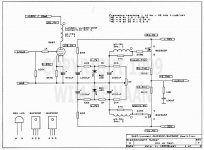
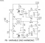
Build the F6 using Nelson's "F6 with Variable 2ND Harmonic" schematic with "ordinary MOSFETs" and the lower (maybe upper too) source resistor with a higher value like 0R47. The FET degeneration will be determined by the Zen pots P3 and P4, not the source resistors. BUT the bias thermal stability will be improved by the DC drop across the source resistor(s). My guess is that this will work without thermistors in the same manner as the many F5s built without thermistors.
Build the F6 using Nelson's "F6 with Variable 2ND Harmonic" schematic with "ordinary MOSFETs" and the lower (maybe upper too) source resistor with a higher value like 0R47. The FET degeneration will be determined by the Zen pots P3 and P4, not the source resistors. BUT the bias thermal stability will be improved by the DC drop across the source resistor(s). My guess is that this will work without thermistors in the same manner as the many F5s built without thermistors.
Has anyone built an F6 with "standard" MOSFETs? What is needed for temperature stability? Will source degeneration be enough or will active thermistor control of the bias be needed?
Attachments
Last edited:
Zen Mod. You are logically correct. lhquam and buzzforb have them too. Fortunately, they are searching for solutions so DIYers [who will never have R100As] can appreciate diyF6. You too have a stake in diyF6. I hope that you augment their efforts so as to keep it alive.well - if you have two pairs of Semisouths , it is finished business for you
and , if made properly - it will outlives you , for sure
Thank you flg.Wim DeHaan's design I posted is a complementary output design. Still a nice idea I will attempt...
This old bull will have to document the performance of the F6 with IRFP240's
so as to keep the DIYers happy.
It will need some output stage degeneration, and more bias voltage on the
voltage sources. Zeners will work fine.
😎
so as to keep the DIYers happy.
It will need some output stage degeneration, and more bias voltage on the
voltage sources. Zeners will work fine.
😎
In a past post regading ACA, this MOSFET was quoted to have a Gm = 2. Will additional voltage gain be needed in this version of diyF6?This old bull will have to document the performance of the F6 with IRFP240's
so as to keep the DIYers happy.
It will need some output stage degeneration, and more bias voltage on the
voltage sources. Zeners will work fine.
😎
I proposed in a past post of this thread the attached schematic in the event additional voltage gain was needed in diyF6. I already bought the PCBs from the DIYAudio store. I hope the schematic is useful for DIYers. One pending question hung: Where's one inject overall loop feedback in it?In a past post regading ACA, this MOSFET was quoted to have a Gm = 2. Will additional voltage gain be needed in this version of diyF6?
Brgds.
Attachments
I think I have the answer to that question and I am doing simulations right now.
Build the F6 using Nelson's "F6 with Variable 2ND Harmonic" schematic with "ordinary MOSFETs" and the lower (maybe upper too) source resistor with a higher value like 0R47. The FET degeneration will be determined by the Zen pots P3 and P4, not the source resistors. BUT the bias thermal stability will be improved by the DC drop across the source resistor(s). My guess is that this will work without thermistors in the same manner as the many F5s built without thermistors.
Ilquam. I think you should try this layout with lateral fets. I started with them. It would be interesting to gt your opinion.
You could go either way pretty easily. The design with undegenerated
Jfets had open loop gain to burn at 39 dB.
😎
Jfets had open loop gain to burn at 39 dB.
😎
This old bull will have to document the performance of the F6 with IRFP240's
so as to keep the DIYers happy.
It will need some output stage degeneration, and more bias voltage on the
voltage sources. Zeners will work fine.
😎
Wow! Papa leaves no stone unturned in supporting his 'followers'. 😀
Especially complimentary followers.
😎
Is that a hint about the next circuit?
Especially complimentary followers.
😎
hawhawhawhaw 🙂 punny! lols
- Home
- Amplifiers
- Pass Labs
- F6 Amplifier