On the Ncore these are not indication lights, but leds used as voltage references! Ga je huiswerk eens even doen!
How about you contribute something instead of just picking the project apart because you have nothing else to do? And Oh btw. Most of us can use google translator... 🙄
So far I like the direction your going Corpius, keep it up 🙂
It would be nice if Corpius made some code public, so the original writers can check if it is theirs!
CODE H i F i D U I N O
Buffalo III - Arduino S/PDIF Input Selection
MCP42010 ? How to control it using Arduino
I hope you're happy now. It's all open source.
I hope that you can contribute something useful to this thread from now on, otherwise I ask you politely to stop polluting it.
Buffalo III - Arduino S/PDIF Input Selection
MCP42010 ? How to control it using Arduino
I hope you're happy now. It's all open source.
I hope that you can contribute something useful to this thread from now on, otherwise I ask you politely to stop polluting it.
do you guys have history? you're just making a dick of yourself ds23man... 🙄
I thought Corpius was pretty open about using modified versions of some public code, you know.... open source/free? in fact afaik the major authors have mostly already all contributed to this very thread already. you are clear on this concept of open source repositories? as I understood it this project was mostly about putting all the hardware and software in the one place...
I thought Corpius was pretty open about using modified versions of some public code, you know.... open source/free? in fact afaik the major authors have mostly already all contributed to this very thread already. you are clear on this concept of open source repositories? as I understood it this project was mostly about putting all the hardware and software in the one place...
Last edited:
Exactly and not to forgot that it also very informative for me.as I understood it this project was mostly about putting all the hardware and software in the one place...
do you guys have history? you're just making a dick of yourself ds23man... 🙄
I thought Corpius was pretty open about using modified versions of some public code, you know.... open source/free? in fact afaik the major authors have mostly already all contributed to this very thread already. you are clear on this concept of open source repositories? as I understood it this project was mostly about putting all the hardware and software in the one place...
Please reread post:
http://www.diyaudio.com/forums/digital-line-level/221559-es9018-i2c-controller-5.html#post3204992
The Ir learning "code" is looking the same as implemented in the LCDuino.....
Don't draw any conclusions when you have not seen the code.Please reread post:
http://www.diyaudio.com/forums/digital-line-level/221559-es9018-i2c-controller-5.html#post3204992
The Ir learning "code" is looking the same as implemented in the LCDuino.....
Linuxworks is not sharing the code and I never asked him to, so I have to write it myself. Which I happen to like doing.
I'm using Ken Shirriff his IR remote library for this and use this code to write the codes to the EEPROM.
EDIT:Besides, the function for devices to learn IR codes is seen in many devices, so nothing special about it
Last edited:
this has been covered and linuxworks (who wrote the code) has been posting in this thread, afaik its public domain whether they like it or not.... but its good manners to respect his wishes, in return i'm sure his feedback will be an asset at some point in the development.
with simple things like the IR learn I would think there are only a limited number of logical ways to do it anyway, so its bound to share some similarity no matter what you do
with simple things like the IR learn I would think there are only a limited number of logical ways to do it anyway, so its bound to share some similarity no matter what you do
I'm really surprised ds23man instead to contribute (diyAudio spirit) only does that criticise and asking copyrights.....
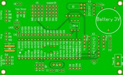
Long radio silence, I know. I've been very busy with all kind of different things, but also a little bit with the controller. Most of the PCB designing have been done, but I need to do some (more) breadboard prototyping in order to know all works like I want it to. I have been struggling a with the remote learning function when working with all the different RC protocols. I'm still not fully satisfied, but I'll get there.
I included a temperature sensor to the PCB, but I don't know if I want to keep it there. Perhaps it's best to have a outbreak with the sensor.
The LT1086 low dropout voltage regulator and a resettable fuse have also been included into the design .
I will post some more details and some pics soon when I find some more time to work on it.
Looking forward to it 🙂
Just thought of something that could be an idea too. A second Voltage regulator circuit for more power hungry display`s.
Just thought of something that could be an idea too. A second Voltage regulator circuit for more power hungry display`s.
Up to 350mA, typical 275mA.
http://media.digikey.com/pdf/Data%20Sheets/Noritake%20PDFs/CU20045-UW5J.pdf
I dont remember where I found the extended data sheet where it stated up to 350mA though.
http://media.digikey.com/pdf/Data%20Sheets/Noritake%20PDFs/CU20045-UW5J.pdf
I dont remember where I found the extended data sheet where it stated up to 350mA though.
I`ll have a closer look at the spec sheet. I am not sure if the LT1086 can power more than the uno`s 7805 wich in some cases fall short due to temp. Should not be a problem though, just thought an additional reg could make it even more rugged 😉
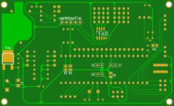
Almost there. I added a DIP switch to allow manual control over stereo/dual mono and volume control on/off. I have to do a few more tests (wish I had some more spare time), but I will order the first PCBs for the prototype this week for sure.
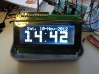
Here are some pics as promised. Also a pic from the RTC function that shows the actual time and date when stand-by mode is entered.
Here are some pics as promised. Also a pic from the RTC function that shows the actual time and date when stand-by mode is entered.
Attachments
That is great. It looks flawless. Looking forward to seeing how it turns out.
I guess you stuck to using the i2c extender for the display connection after all?
I`ll update the model later on. I think I will get the controller this week. It somehow took more than 2 weeks for it to go from HK to Norway. By this rate I will get your new controller finished before I get the remaining items for the shield lol.
I will stick to local suppliers from now on I think.
CODE H i F i D U I N O
Buffalo III - Arduino S/PDIF Input Selection
MCP42010 ? How to control it using Arduino
I hope you're happy now. It's all open source.
I hope that you can contribute something useful to this thread from now on, otherwise I ask you politely to stop polluting it.
That's very nice of you to share your design. Sure look interesting since I am also trying to learn the Arduino.
When I order some parts from HK it always takes two weeks or more. Luckily I do order most parts at a local shop. 🙂That is great. It looks flawless. Looking forward to seeing how it turns out.
I guess you stuck to using the i2c extender for the display connection after all?
I`ll update the model later on. I think I will get the controller this week. It somehow took more than 2 weeks for it to go from HK to Norway. By this rate I will get your new controller finished before I get the remaining items for the shield lol.
I will stick to local suppliers from now on I think.
The i2c extender. For now I´ll stick to using the extender from electroFUN, but in my final design I´ll incorporate a small IO extender to the design and use it in a similar way as the extender from E-Fun. The only difference will be the connections to the LCD. I will add a row of connectors that line up with the LCD's connectors. In my opinion this is the best way to connect the LCD to the controller.
- Status
- Not open for further replies.
- Home
- Source & Line
- Digital Line Level
- ES9018 I2C controller