IR codes... I have managed to record the codes of all different IR protocols I have available and use them, but in some cases they are not very reliable. The response is also quite slow which bothers me a lot. I have put is aside for a moment and let it rest until I finished the interface of the controller. After that I will dive into the IR codes again.
Ah, ok. I was just wondering. Looking forward to the boards 🙂
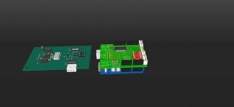
In the meantime, I have the shield. I updated the Shield model with some JST PH connectors as well.
Attachments
Here's a little preview: CE644 controller - YouTube
Outstanding! I think I need to get one of them displays for my project.
My wife does not like my friendly case at all...the one that waves at you...
I took my DAC with HiFiDuino/Corpius code and Apple remote to a friends house over the weekend. We found a remote from a Squeezebox 2 would cause the source to switch on my DAC. The Apple remote had no effect on the older SB. We didn't notice it at first and suspected hardware difficulties.😕
Last edited:
In the meantime, I have the shield. I updated the Shield model with some JST PH connectors as well.
Nice work on the models gwikse! That shield has simplified my build.
Yes those displays are really nice. Almost as good as a vfd display. OK, now I'm exaggerating. 😀 I don't like most lcd displays as the are too bright imo.Outstanding! I think I need to get one of them displays for my project.
My wife does not like my friendly case at all...the one that waves at you...
I took my DAC with HiFiDuino/Corpius code and Apple remote to a friends house over the weekend. We found a remote from a Squeezebox 2 would cause the source to switch on my DAC. The Apple remote had no effect on the older SB. We didn't notice it at first and suspected hardware difficulties.😕
I'm aware of the DAC reacting to the squeezebox remote. It also reacts on the remote of my TV when I set the volume down. When I finish the gui I'll start working on the remote stuff again.
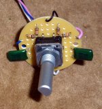
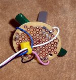
I have hardware debounce ready to go. This is per glt's helpful diagram. The next picture of the new encoder will have holes in the PCB for them mounting lugs. So when you tighten the nut while holding the circuit board, the encoder doesn't turn.😱 Fortunately I left my other software debounce encoder intact.
http://hifiduino.files.wordpress.com/2010/10/rotenc.jpg
http://hifiduino.files.wordpress.com/2010/10/rotenc.jpg
Attachments
Last edited:
FIR filter (sharp & slow roll of) can be set for PCM. For DSD you can set the IIR bandwidth (50, 60 & 70k)Corpius the controller can select differents FIR for DSD?
Yes, that is possible. The IIR bandwidth can be set to Normal (47k), 50k, 60k, and 70k. For DSD it is recommended to set it from 50k to 70k. Use normal (46k) for PCM.
Sabre32 H i F i D U I N O
I'm planning to program it in a way that when the input format is DSD 50K is automatically is selected, but another setting can also be chosen. When the input format is PCM it should select Normal (47k) automatically.
Sabre32 H i F i D U I N O
I'm planning to program it in a way that when the input format is DSD 50K is automatically is selected, but another setting can also be chosen. When the input format is PCM it should select Normal (47k) automatically.
Have you tried it yet?I have hardware debounce ready to go. This is per glt's helpful diagram. The next picture of the new encoder will have holes in the PCB for them mounting lugs. So when you tighten the nut while holding the circuit board, the encoder doesn't turn.😱 Fortunately I left my other software debounce encoder intact.
http://hifiduino.files.wordpress.com/2010/10/rotenc.jpg
Have you tried it yet?
Yes, but only the volume works. I had pulled out the center terminal on the encoder so no push button works to select menu. I am waiting for replacement encoder to arrive. With the holiday Thursday it might not be until next week.
Yes, but only the volume works. I had pulled out the center terminal on the encoder so no push button works to select menu. I am waiting for replacement encoder to arrive. With the holiday Thursday it might not be until next week.
Use a separate switch...
Yes, that is possible. The IIR bandwidth can be set to Normal (47k), 50k, 60k, and 70k. For DSD it is recommended to set it from 50k to 70k. Use normal (46k) for PCM.
Sabre32 H i F i D U I N O
I'm planning to program it in a way that when the input format is DSD 50K is automatically is selected, but another setting can also be chosen. When the input format is PCM it should select Normal (47k) automatically.
That's sound great.🙂
Have you tried it yet?
The new encoder arrived yesterday! First thing I did was drill two holes in the PCB for them two lugs on the switch body. Now it won't twist when I hold the board and snug the nut. I am using the Panasonic EVQ-WTEF2515B rotary encoder that glt suggested.
I disabled the pull up resistors in the Arduino by setting the appropriate two lines of code to LOW. I reset switchbounce interval from 250 to 200. Hardware debounce works better for me. Better control. I get less overshoot, ghost changes, when turning the encoder. With software debounce, after I made a change to a menu setting sometimes it changed back to previous setting even though I didn't turn the encoder another click. I’ll stay with hardware debounce.
One thing the knob I am getting from modushop is 6mm splined so I may have to go splined encoder shopping. Not sure how the Panasonic with the half flat shaft will work with that knob. I had a cavity machined in the front panel around the flange of the knob so it cannot be off center or it will rub.
I'm using the exact same encoder. Two new encoders just arrived some days ago. I never experience any ghost changes when turning the encoder, but that doesn't stop me from using the hardware debounce.🙂The new encoder arrived yesterday! First thing I did was drill two holes in the PCB for them two lugs on the switch body. Now it won't twist when I hold the board and snug the nut. I am using the Panasonic EVQ-WTEF2515B rotary encoder that glt suggested.
I disabled the pull up resistors in the Arduino by setting the appropriate two lines of code to LOW. I reset switchbounce interval from 250 to 200. Hardware debounce works better for me. Better control. I get less overshoot, ghost changes, when turning the encoder. With software debounce, after I made a change to a menu setting sometimes it changed back to previous setting even though I didn't turn the encoder another click. I’ll stay with hardware debounce.
One thing the knob I am getting from modushop is 6mm splined so I may have to go splined encoder shopping. Not sure how the Panasonic with the half flat shaft will work with that knob. I had a cavity machined in the front panel around the flange of the knob so it cannot be off center or it will rub.
I do not think that the knob fits onto the encoders shaft. You could order another encoder or another knob. I recently orders some knobs from ebay.
30x22mm Aluminum Knob Solid 1/4 Shaft Volume Tone Control Audio Tube AMP Black | eBay
These have a little screw on the side to fix the knob to the encoders shaft. I will use these knobs with the yet to be CNC'd frontplate
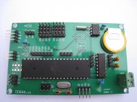
Et viola! The PCB is here......finally
It took a real long time before the mailman showed up with the Prototype PCB. I almost gave him a hug when he handed over the small box from China.
I did a quick check on all connections and all looks fine at first sight.
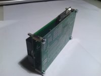
It fits exactly on my 20x4 LCD and the pins of the 'I2C LCD extra IO' do line up perfectly with the connector pads. Time to do some prototyping tomorrow.
I also have to do some more programming, but most of it is done by now.
Here are some 'showcase' pics of the PCB mounted on the LCD display.
It took a real long time before the mailman showed up with the Prototype PCB. I almost gave him a hug when he handed over the small box from China.
I did a quick check on all connections and all looks fine at first sight.
It fits exactly on my 20x4 LCD and the pins of the 'I2C LCD extra IO' do line up perfectly with the connector pads. Time to do some prototyping tomorrow.
I also have to do some more programming, but most of it is done by now.
Here are some 'showcase' pics of the PCB mounted on the LCD display.
Attachments
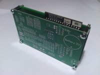
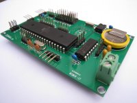
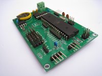
I populated one of the boards today to test if no mistakes where made in the design. All components fit nicely,exept for the 100nf caps I had at home. The pin spacing for most 100nf caps is a bit wider (5.04mm) than the distance between the holes (2.52mm) for the caps. The pins of the caps I had at home needed to be bend straight in order to fit in the holes, but 100nf caps with a pin spacing of 2.52mm can also be bought 🙄
I had ordered the wrong package LT1086, so this is not used yet. The meant that I had to power it by bypassing the power input. I used an Arduino for this. All works just like it has to. Now to add the temperature sensor and DIP switch. I decided to use to DIP switch to lock the volume control enable/disabled setting, Stereo/Dual Mono setting and output phase setting. When the switch is set to ON the corresponding setting can't be accessed in the menu. This safety precaution is especially useful when having children around or a wife that is not that confident with electronics or.... to protect it from yourself
I also need to finish the code, It's still not finished because I think of options and setting to add or enhance about every two days. I hope to release the first version next week.
Attachments
Very nice. It looks like it will be possible to have a very tidy cable layout. Nice and tidy control solution that fits the rear of a 20x4. Very nice 😀
I like the idea of locking the settings that can harm the system as well. Less likely that there will be any mishaps 🙂
I like the idea of locking the settings that can harm the system as well. Less likely that there will be any mishaps 🙂
- Status
- Not open for further replies.
- Home
- Source & Line
- Digital Line Level
- ES9018 I2C controller