I wonder if the F2J can give us an idea of a good operating point for the F6. I ASSume that he fine tuned that circuit based on sound and have been told by another member thta it is his favorite Pass amp. Just wondering. I am going to give it a try tonight. Why not.
😀 its gotten boring. Just wanted to liven the discussion with stupidity. For real do. If we operate the top fet as a modulated CS for the bottom fet....ah never mind.
so you probably mixed that number in F2 ....
anyway , idea is good , but certainly for another amp and another thread
"look Ma, I have those nice BudP's xformers ..... can I make ya new juice maker with them !?"
(my approach - wherever ya see a hole , put a pair of nice signal xformers . today's amps are full with holes )

anyway , idea is good , but certainly for another amp and another thread
"look Ma, I have those nice BudP's xformers ..... can I make ya new juice maker with them !?"
(my approach - wherever ya see a hole , put a pair of nice signal xformers . today's amps are full with holes )
So it is sage to say(as i was about to pummel you with schematics) that maintaining Symetrical drive of xformer is main design gole?
Edit:
One thing the F6 does that I like is create space or perhaps reveal space in good recordings.
Edit:
One thing the F6 does that I like is create space or perhaps reveal space in good recordings.
Last edited:
I'm not making any sort of agenda here ;
remember , you're the one who started with few last posts ......
xformer is either plain stupid , or overly superior , in attitude to life & everything - he doesn't know and doesn't care what's on primary and secondary , as long temperature is not rising
so - choices are yours
remember , you're the one who started with few last posts ......
xformer is either plain stupid , or overly superior , in attitude to life & everything - he doesn't know and doesn't care what's on primary and secondary , as long temperature is not rising
so - choices are yours
Your circuit is simple, robust and delivers great performance and sound. Mr. Pass may release his schematic in the future. In the interim you and others are telling the world of diyAudio the bigger potential of Teaser-6 and Franken6. Have you cast anything/performance in stone? You and buzzforb, ZM, and others are/have been the source of valuable info; not Mr. Pass. Who is gonna tell/show us how Teaser-6 and Franken6 perform as a Class A/B. Will it be Mr. Pass? I feel priviliged [and hope that others also do ] that you and others are sharing valuable info about your rendition of Conceptual F6. I care about what you, buzzforb and others are doing. I can't care about what Mr. Pass is doing because I know nothing about his activity, and thus why care about a high level secret; albeit valuable? I care about the proverbial bird at hand [Teaser6, Franken6] and not the one on a distant tree [F6 by Mr. Pass].The challenge that I am undertaking is to Guess where Nelson is taking us. That means KISS (Keep It Simple, Stupid) and quality, which involves trade-offs. I suspect that Papa will show a circuit that is even simpler and better than mine shown in post #1647 http://www.diyaudio.com/forums/pass-labs/216616-f6-amplifier-165.html#post3159810.
what you are going to do with the bird ?
keep it in cage ?
as long you can see it , with naked eye or .... , any bird is same good .
point is in looking at it , not having prettiest one
you started to look at one of yours , recently - Compound amps .
keep it in cage ?
as long you can see it , with naked eye or .... , any bird is same good .
point is in looking at it , not having prettiest one
you started to look at one of yours , recently - Compound amps .
Using a hint from Nelson's "F6 Conceptual Schematic" about V2+ and V2-, I came up with another approach to the bias voltage generation using TL431 voltage regulators in a TO-92 package. This generates both the reduced voltages for the input JFETs and regulated voltages for the bias circuits, making it very insensitive to the V1, V2 rail voltage fluctuations.
Attachments
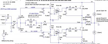
Using a hint from Nelson's "F6 Conceptual Schematic" about V2+ and V2-, I came up with another approach to the bias voltage generation using TL431 voltage regulators in a TO-92 package. This generates both the reduced voltages for the input JFETs and regulated voltages for the bias circuits, making it very insensitive to the V1, V2 rail voltage fluctuations.
do you get a significant change in performance?
The difference is more tolerance to rail voltage variations. No known difference otherwise.do you get a significant change in performance?
Last edited:
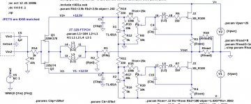
I decided that it was a bad idea to try to economize on the resistor count by connecting the TL431 REF pin to the bias circuit potentiometer. Here is a revised schematic. This also restores the resistor charging the bias capacitor to somewhere near 10K ohms.
Attachments
ZM. We are into philosophy, and it is all right. I am not telling any DIYer to do anything. You DIYers are the football, soccer and basketball stars on the field, and excell at what you do. I am a fan and an observer cheering and celebrating your achievements. I point connections and possible direction which are still within the bounds of the thread. lhquam has a clear objective to guess the design of Mr. Pass. What if Mr. Pass is operating his F6 in Class A/B? Slim chance in the possible view of many of you; but a possibility nonetheless because it was practiced with the old classic [nothing new] and sounded great.what you are going to do with the bird ?
keep it in cage ?
as long you can see it , with naked eye or .... , any bird is same good .
point is in looking at it , not having prettiest one
you started to look at one of yours , recently - Compound amps .
I hope the comment you made on my thread Compound Power Amps is good. I did not understand it fully. It is a privilige for me to write on diyAudio; just like driving a car in the U.S.A. In all of my threads, I communicate ideas [some are weird], attach them with experiments and results like you, lhquam and others have done and continue to do. My posts are up for grabs by any DIYer to practice, laugh at, ridicule , enjoy etc. I am not selling anything; just passing therapeutic time.
Last edited:
Since my amplifier power needs are happily satisfied with less than 25W, I have no real interest in spending (wasting) time of Class-AB circuits. 
Your circuit is simple, robust and delivers great performance and sound. Mr. Pass may release his schematic in the future. In the interim you and others are telling the world of diyAudio the bigger potential of Teaser-6 and Franken6. Have you cast anything/performance in stone? You and buzzforb, ZM, and others are/have been the source of valuable info; not Mr. Pass. Who is gonna tell/show us how Teaser-6 and Franken6 perform as a Class A/B. Will it be Mr. Pass? I feel priviliged [and hope that others also do ] that you and others are sharing valuable info about your rendition of Conceptual F6. I care about what you, buzzforb and others are doing. I can't care about what Mr. Pass is doing because I know nothing about his activity, and thus why care about a high level secret; albeit valuable? I care about the proverbial bird at hand [Teaser6, Franken6] and not the one on a distant tree [F6 by Mr. Pass].
Oops, the bottom cap (C2) should connect to V-, not ground. I am still tweaking a few things about this schematic, mostly resistor values.
The general idea looks pretty good.
The general idea looks pretty good.
I decided that it was a bad idea to try to economize on the resistor count by connecting the TL431 REF pin to the bias circuit potentiometer. Here is a revised schematic. This also restores the resistor charging the bias capacitor to somewhere near 10K ohms.
- Home
- Amplifiers
- Pass Labs
- F6 Amplifier