One other thought. If it turns out that resistor/capacitor order changes the character of the sound, would it be possible to make the board capable of both options?
Not in a clean way and not easily, IMHO.
It's for this reason that I've asked others to try... to make a choice.
BTW if tomorrow I'll have the same results and coeherent reports there is nothing to regret in swapping those two positions... 😉
The output voltage/current phase relationship is the cause of the difference. When we get to finer aspects of design, we cannot treat these as black boxes, rather more deeper look into the operations is required. Although I have not tried it on the MyRef, I knew it would make a meaningful difference. When the tuning is right, you start to feel the emotion the performer puts into a performance, much more difficult to describe in usual audio terms.That's interesting, as there does not seem to be a technical reason for the sound change other that different interference (well, self interference maybe). You used the same identical two parts and just temporarily resoldered them with swapped positions?
Remember it's series connected parts, it's a black box with two connections only, no way for the current to change or "escape" other than by interference of some sort (which, OTOH, would have to be gross to be that effective).
...
..........When we get to finer aspects of design, we cannot treat these as black boxes, rather more deeper look into the operations is required. Although I have not tried it on the MyRef, I knew it would make a meaningful difference. When the tuning is right, you start to feel the emotion the performer puts into a performance, much more difficult to describe in usual audio terms.
A little off topic - I've owned Miles Davis "Seven Steps to Heaven" since 1963 and can sing/hum almost every note on the album. Today I heard the emotion (Harmon Mute solo) on a ballad like never before. We are truly moving in the right direction. Right on soongsc!
Last call
Today me, bmcbob and suburra tested the C9/R10 mod without reaching the full agreement on it.
One of the testers also had strange heating problems.
So the boards going to production will have, as default, the original C9/R10 arrangement but I've managed to make possible also the modded one at the price of omitting C21 (C9 optional bypass).

This is the last call for opinions, comments and suggestions.
Tomorrow I'll order the boards.
Today me, bmcbob and suburra tested the C9/R10 mod without reaching the full agreement on it.
One of the testers also had strange heating problems.
So the boards going to production will have, as default, the original C9/R10 arrangement but I've managed to make possible also the modded one at the price of omitting C21 (C9 optional bypass).
This is the last call for opinions, comments and suggestions.
Tomorrow I'll order the boards.
Attachments
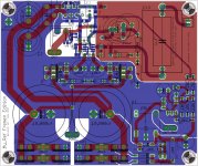
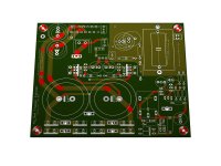
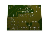
Im sure you have stated this elsewhere, but I have kind of a silly question. What color are the boards going to be?
Im sure you have stated this elsewhere, but I have kind of a silly question. What color are the boards going to be?
Exactly like beta ones:
Can you elaborate on what different opinions were there?Today me, bmcbob and suburra tested the C9/R10 mod without reaching the full agreement on it.
One of the testers also had strange heating problems.
...
Can you elaborate on what different opinions were there?
I and one of the testers found the new arrangement an improvement:
- More focus
- Bigger soundstage
- Veil lifted effect
- More musical
- Thin and unmusical
- Can't stand listening to more than one track
Are you sure the other one moved the bypass cap as well? If not, you end up with the value of the bypass cap instead of C9. I would expect that impression in such case. Even you can try that.
Are you sure the other one moved the bypass cap as well? If not, you end up with the value of the bypass cap instead of C9. I would expect that impression in such case. Even you can try that.
None of the testers had C21 populated.
Dario,
Sounds like a great solution. Thank you.
Regarding C21, can you discuss what it's function was? why it was optional?
Also, would it make sense to add C21 by wiring point to point in parallel with C9?
None of questions are intended to change the board design. Just curiosity. And maybe some thing to try on a beta board while we wait for the RC boards to be manufactured.
I'm getting excited with the ordering of the boards.
I allege and have done so before that the ratio of C13:C9 is "wrong". I further allege that testing with the "wrong" ratio will result in, at best, a skewed conclusion and at worst a worthless conclusion.
Will anyone on the testing team install the correct capacitor ratio and report on whether C9 needs to be in one location or another?
For reference here is the formula predicting the minimum value for C9:
C9 >= C1 * sqrt(2) * R13 / R10.
For C1=1uF, R13=100k & R10=390r then C9>=360uF, use 470uF
Will anyone on the testing team install the correct capacitor ratio and report on whether C9 needs to be in one location or another?
For reference here is the formula predicting the minimum value for C9:
C9 >= C1 * sqrt(2) * R13 / R10.
For C1=1uF, R13=100k & R10=390r then C9>=360uF, use 470uF
Last edited:
I allege and have done so before that the ratio of C13:C9 is "wrong". I further allege that testing with the "wrong" ratio will result in, at best, a skewed conclusions and at worst a worthless conclusion.
Hi Andrew,
I've asked Mauro about your different calculation of C9 value some weeks ago but I forgot to post about it, sorry.
He answered that he prefer to calculate and verify with distortion measurements rather than blindly applying the empiric theories of Cordell and Self...
The actual values are the ones that best suited his project goals (verified with measurements).
Please, do not shoot the ambassador... 😉
Sounds like a great solution. Thank you.
You're welcome, Jac.
Regarding C21, can you discuss what it's function was? why it was optional?
C9 is one of the most critical cap (soundwise) in this design.
Mauro himself suggested to try a bypass to improve C9 performance.
It was optional since with Black Gates bypassing is not recommended and also for other caps bypassing is a mixed bag.
For the my ref I've empirically found a best value of 22nF but as for every bypass you often improve some aspects and worsen others.
Also, would it make sense to add C21 by wiring point to point in parallel with C9?
Maybe, it depends on the particular capacitor used.
I'm getting excited with the ordering of the boards.
Me too... 😉
This last hours before the order are frenetic, lot of tiny details to verify...
I repeat
Will anyone on the testing team install the correct capacitor ratio and report on whether C9 needs to be in one location or another?
I would like to see your personal listening or measurement experience on this design. I get the impression you have the boards, why not share your actual experience with them?I repeat
Here is the rest of the story.
I’m the odd man out with my test results. I had trimmed the leads on the Blackgates too short to reach the span of the sockets for R10. I did a jerry rig by extending them with some leftover Renkin wire. When I initially heard the sound of the new positioning, I was quite impressed. As I normally don’t trust what I hear till after a 30 t0 40 minute warm-up, I left the room and let the music play. Within two minutes I heard the thermal protection start to trigger.
I shut down the amps and got my IR temp gauge. The second try produced triggers on one amp at ~ 72-73, while the other gets up to 81C or more. There shouldn’t be that much of a spread between the two. Both amps were triggering even with the difference in temps. I then let the amp cool to room temps and tried again – this time watching the temp rise while listening. The sound could be heard to deteriorate as the temps went up, and again both amps started to trigger.
I then reset the positioning to the standard/original configuration. Everything cleared up and the temps stabilized. I could play several tracks with no problem.
Reversed the placement again and the heating problem reappeared. The sound was never as good as the first time I tested the new positioning and the sound was truly awful. The reason I didn’t make it through a single track though, was the triggering not the sound quality. What I could hear was thin, scratchy, and loaded with distortion.
Back to the original and they played with perfect operation for the next four hours.
Dario’s dual placement option is a good solution, but we really need more than the two existing builds in order to drill down on the problem. Also, if anyone has the simulation software to test the alternatives, that would be very helpful.
I should also mention that I installed the Caddocks as per the BOM at R13 and the results were stunning. That Caddock really made a big improvement. The sound is sweeter/warmer and the clarity seems to be better. The stage sounds more real and the cymbals sound less metallic and have a thicker character. That’s a really significant position.
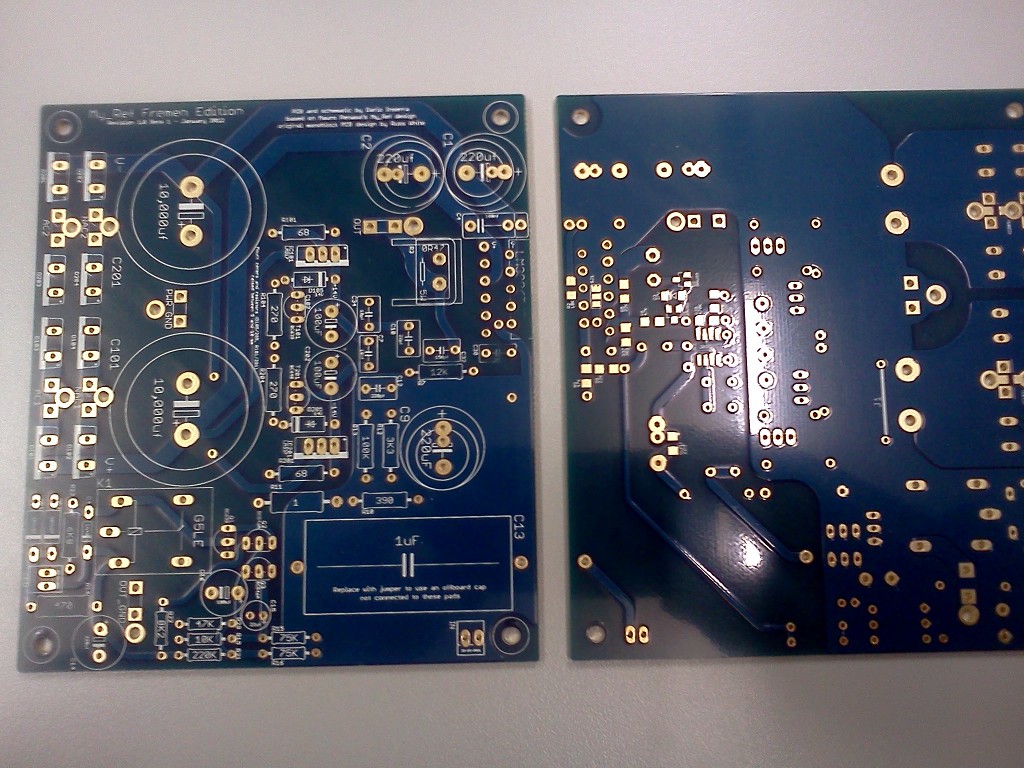
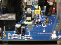
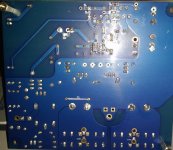
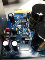
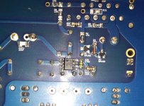
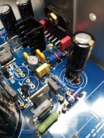
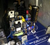
Here are some photos of how things stand presently. If you see something - say something.
I’m the odd man out with my test results. I had trimmed the leads on the Blackgates too short to reach the span of the sockets for R10. I did a jerry rig by extending them with some leftover Renkin wire. When I initially heard the sound of the new positioning, I was quite impressed. As I normally don’t trust what I hear till after a 30 t0 40 minute warm-up, I left the room and let the music play. Within two minutes I heard the thermal protection start to trigger.
I shut down the amps and got my IR temp gauge. The second try produced triggers on one amp at ~ 72-73, while the other gets up to 81C or more. There shouldn’t be that much of a spread between the two. Both amps were triggering even with the difference in temps. I then let the amp cool to room temps and tried again – this time watching the temp rise while listening. The sound could be heard to deteriorate as the temps went up, and again both amps started to trigger.
I then reset the positioning to the standard/original configuration. Everything cleared up and the temps stabilized. I could play several tracks with no problem.
Reversed the placement again and the heating problem reappeared. The sound was never as good as the first time I tested the new positioning and the sound was truly awful. The reason I didn’t make it through a single track though, was the triggering not the sound quality. What I could hear was thin, scratchy, and loaded with distortion.
Back to the original and they played with perfect operation for the next four hours.
Dario’s dual placement option is a good solution, but we really need more than the two existing builds in order to drill down on the problem. Also, if anyone has the simulation software to test the alternatives, that would be very helpful.
I should also mention that I installed the Caddocks as per the BOM at R13 and the results were stunning. That Caddock really made a big improvement. The sound is sweeter/warmer and the clarity seems to be better. The stage sounds more real and the cymbals sound less metallic and have a thicker character. That’s a really significant position.
Here are some photos of how things stand presently. If you see something - say something.
Attachments

C9 is an electrolytic capacitor, basically these operate more linearly when there is a DC bias across them. C21 is an option to improve linearity because in this circuit it seems that C9 does not have DC across it.Dario,
Sounds like a great solution. Thank you.
Regarding C21, can you discuss what it's function was? why it was optional?
Also, would it make sense to add C21 by wiring point to point in parallel with C9?
None of questions are intended to change the board design. Just curiosity. And maybe some thing to try on a beta board while we wait for the RC boards to be manufactured.
I'm getting excited with the ordering of the boards.
- Status
- Not open for further replies.
- Home
- Amplifiers
- Chip Amps
- My_Ref Fremen Edition - Beta build/Fine tuning