 I'm one of those sensitive musician types and I might go over the edge.
I've heard that some of the best musicians live on the edge. Why should you be any different from the geniuses?
 That makes me feel much more betterer
 You are lucky they don't try to change your typing. The computer tries to correct my Chinese, I have a hard time checking and correcting it.🙄In the third grade Mrs. Haffy told me to put more time on my spelling workbook. Sometimes we see what we think and not what we type.😱 Those da*m spell checkers can't read my mind either.😀
Every mV accross R11 appears 1:1 at the output (it easy to see the circuit is a voltage follower for signal appearing accross R11). What R11 does, though, is reducing shield current in the interconnect when both source and amp are earth-grounded at different points or have impressed current from other low impedance mechanisms (ground loops from improper high loop area cabling). Since LF drops along the shield's ohmic resistance are input signal, too, plus then undergo some 30x of amplification, a net reduduction of hum/buzz may be achieved in some special situations. The typical "it depends" kind of thing. A good way to fix this is using an balanced cable together with a true differential input.R11:
It's needed and improves noise rejection from GND by several tens dB.
-------:-------
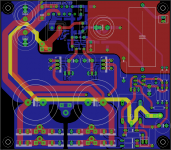
As for speaker return current minimized loop area, see pic for the strategy (which is simple : keep send and return lines together). This is done by wiring at the bottom side of the PCB, no PCB change is necessary. Now it is drawn as a dead short, of course you must tee off the speaker send and return -- as a twisted pair -- at some point (but it does not matter where).
There is something non-perfect there, still : the run allong asymetric lengths of V+ and V- lines, as well as the too big loop area of the GND plane vs supplies itself.
Exact position would have to be found experimentally**) by injecting a magnetic field then moving the wire until lowest output is achieved.
But to fix this on the PCB, it would be a major workaround, a complete rewrapping of signal and power paths... resulting in a short but wide PCB where power/relay stuff is left of the LM's and signal is right of them, strictly adhering to the star GND principle as well....
**) speaking of which, I'm OK again and will continue working on the PCB tomorrow....
Attachments
Well, "big hopes" is a strong term but striving for layout/wiring which gives lowest possible interference (which can be quantified by measurement) has little chances to degrade perceived performance and is a prerequisite before any tweaking with boutique parts (and resistor orientation and similar things) makes sense. Some aspects of that are somewhat interconnected there, of course. And striving for the best circuit comes even before the layout/wiring, but in this thread we take the ciruit design as a given.
But that's only me, of course.
But that's only me, of course.
Last edited:
KSTR, I have often wondered if balanced cables would make an audible difference with this or any MyRef/LM3886 design. Hopefully that subject will get some attention as things develop.
Last edited:
First impressions on the C9/R10 mod
I've started to test the C9/R10 mod and for sure it sound different.
With the position reversed (C9 to ground) there seem to be a more contrasted, direct sound with wider and deeper soundstage and tighter bass.
The classic arrangement seems more 'soft', maybe confused.
So far I would say Klaus'mod is effective in improving sound but I'll decide after listening again tomorrow... I don't want another ceramics debacle... 😉
But we don't have a differential input here... 😕
We could test it with RC boards but I really don't think this is a major issue.
This sort of things can be addressed only using a quite bigger board, I fear.
Limits given I don't feel it's a bad layout, is it?
Sorry, I can't understand to what are you referring to...can you clarify?
I'll read with interest your tests results 🙂
Well, in the core part (the amp one) circuit is given, since I'm designing a My_Ref variant that try to be, nevertheless, faithfull to Mauro's design (some mods are inspired by the Evolution too).
Though it doesn't mean that the amp section can't be modified or improved.
In fact:
I've started to test the C9/R10 mod and for sure it sound different.
With the position reversed (C9 to ground) there seem to be a more contrasted, direct sound with wider and deeper soundstage and tighter bass.
The classic arrangement seems more 'soft', maybe confused.
So far I would say Klaus'mod is effective in improving sound but I'll decide after listening again tomorrow... I don't want another ceramics debacle... 😉
Every mV accross R11 appears 1:1 at the output
(...) The typical "it depends" kind of thing. A good way to fix this is using an balanced cable together with a true differential input.
But we don't have a differential input here... 😕
As for speaker return current minimized loop area, see pic for the strategy (which is simple : keep send and return lines together). This is done by wiring at the bottom side of the PCB, no PCB change is necessary. Now it is drawn as a dead short, of course you must tee off the speaker send and return -- as a twisted pair -- at some point (but it does not matter where).
We could test it with RC boards but I really don't think this is a major issue.
There is something non-perfect there, still : the run allong asymetric lengths of V+ and V- lines, as well as the too big loop area of the GND plane vs supplies itself.
Exact position would have to be found experimentally**) by injecting a magnetic field then moving the wire until lowest output is achieved.
This sort of things can be addressed only using a quite bigger board, I fear.
Limits given I don't feel it's a bad layout, is it?
**) speaking of which, I'm OK again and will continue working on the PCB tomorrow....
Sorry, I can't understand to what are you referring to...can you clarify?
I'll read with interest your tests results 🙂
Some aspects of that are somewhat interconnected there, of course. And striving for the best circuit comes even before the layout/wiring, but in this thread we take the ciruit design as a given.
Well, in the core part (the amp one) circuit is given, since I'm designing a My_Ref variant that try to be, nevertheless, faithfull to Mauro's design (some mods are inspired by the Evolution too).
Though it doesn't mean that the amp section can't be modified or improved.
In fact:
- an alternate compensation is offered (it modify not by a small margin how the amp works)
- LM3886 grounding is different.
- A voltage limiter has been introduced to permit higher rails on LM318
- Your C9/R10 mod is going to be part of it.
Last edited:
Bob,
A MyRef, as well as any other OpAmp design, could be modified to be a differential input (even and especially for a unbalanced source output). There are some issues though (like you need to know the source impedance which must be fixed, and for the MyRef you'd need a permanently attached cable).
It would probably be easier and more generally useful to put a high impedance differential input/buffer ahead of a MyRef (which could be either the subtracting circuit itself or the input circuit does the subtraction). Many ways to skin a cat here....
That's interesting, as there does not seem to be a technical reason for the sound change other that different interference (well, self interference maybe). You used the same identical two parts and just temporarily resoldered them with swapped positions?I've started to test the C9/R10 mod and for sure it sound different.
With the position reversed (C9 to ground) there seem to be a more contrasted, direct sound with wider and deeper soundstage and tighter bass.
The classic arrangement seems more 'soft', maybe confused.
So far I would say Klaus'mod is effective in improving sound but I'll decide after listening again tomorrow... I don't want another ceramics debacle... 😉
Remember it's series connected parts, it's a black box with two connections only, no way for the current to change or "escape" other than by interference of some sort (which, OTOH, would have to be gross to be that effective).
I would think it could be same total area or even smaller, there is quite some unused area on the PCB right now in the PSU section.This sort of things can be addressed only using a quite bigger board, I fear.
No, it is not a bad layout, no need for headaches here. But it might not be the best possible (with the definition of "best" being a variable as every designer has his own preferences -- it's more about best compromises, in the end).Limits given I don't feel it's a bad layout, is it?
I still have not had the board running from transformer alone, and have not played with rewiring and have not done any tests and measurement other than what I wrote about last Monday.Sorry, I can't understand to what are you referring to...can you clarify?
I'll read with interest your tests results 🙂
That's interesting, as there does not seem to be a technical reason for the sound change other that different interference (well, self interference maybe). You used the same identical two parts and just temporarily resoldered them with swapped positions?
I'm using sockets, the very same reistors and identical, but two different pair of Panasonic FM.
Tomorrow I'll try with different caps and I'll use the same pair.
I would think it could be same total area or even smaller, there is quite some unused area on the PCB right now in the PSU section.
Maybe in the next days you can draw a simple schema, in this moment I can't figure how you would do it.
No, it is not a bad layout, no need for headaches here. But it might not be the best possible (with the definition of "best" being a variable as every designer has his own preferences -- it's more about best compromises, in the end).
I'm sure it's not the best possible layout! 😀
In fact it's my first layout at all... and I'm not a professional too 😉
I still have not had the board running from transformer alone, and have not played with rewiring and have not done any tests and measurement other than what I wrote about last Monday.
I know, I was referring to your future tests. 😉
Attachments

Oh, I did not know that. Given this info, it is a fantastic layout, then 😉In fact it's my first layout at all... and I'm not a professional too 😉
BTW, did you give the 220uF caps some re-forming time (1hr at rated voltage) before usage? If not, that could explain some of the differences you heard.
Oh, I did not know that. Given this info, it is a fantastic layout, then 😉
Thanks 🙂
I've read tens of application notes, whitepapers, studied tens of PCB layouts from my Service Manual collection and received some help (not as much as I hoped though) on the threads too.
BTW, did you give the 220uF caps some re-forming time (1hr at rated voltage) before usage? If not, that could explain some of the differences you heard.
Both pairs were brand new with same date code.
Tomorrow tests with the same pair will resolve this doubt. 😉
Just to be sure...
I think I've already wrote it... BTW to all partecipants:
Don't buy BOM until I declare it final (it will be next week).
Some parts have changed and until I order boards (and, maybe, some days further) other could change.
I think I've already wrote it... BTW to all partecipants:
Don't buy BOM until I declare it final (it will be next week).
Some parts have changed and until I order boards (and, maybe, some days further) other could change.
I think I've already wrote it... BTW to all partecipants:
Don't buy BOM until I declare it final (it will be next week).
Some parts have changed and until I order boards (and, maybe, some days further) other could change.
I admit to aquiring some of the more speciallized bits like capacitors in advance, but I agree, we need to wait until things firm up before buying the majority of parts.
Bob,
Relative to Klaus' comment on a balanced input approach, check out the schematic on the Twisted Pear Sympatico amp. I think this is very close to what Klaus was talking about, i.e., balanced throughout, input buffers, fully differential op-amps in the loop with chip amps just like a My Ref. I am in the process of converting my system to balanced with the amps located at the speakers. I admit I was pretty tempted by the Twisted Pear solution, but then who can resist the team approach and the chance to hear the listening opinions of others, such as yourself? 🙂
Jac
I admit to aquiring some of the more speciallized bits like capacitors in advance, but I agree, we need to wait until things firm up before buying the majority of parts.
Hi Jac,
most of the components are unlikely to change but it would be a pity be forced to do a second Mouser order for a part or two...isn't it? 😉

It rains... so I didn't go to dance Salsa... what can I do? 🙄
I've tried again the C9/R10 mod with Nichicon FWs (single pair).
Same impressions... 🙂
Let's see if tomorrow it will be confirmed.
In the meanwhile others are (going to) testing it and will report tomorrow.
I've tried again the C9/R10 mod with Nichicon FWs (single pair).
Same impressions... 🙂
Let's see if tomorrow it will be confirmed.
In the meanwhile others are (going to) testing it and will report tomorrow.
If I am thinking about this correctly, perhaps we shouldn't be surprised that changing the order of a resistor and a capacitor in series. True, together they form a filter. But individually they each react to the input signal, the input impedance, and the output impedance that they are feeding. When we swap the resistor and capacitor, don't we change the signal going to each element and, therefore, it's response to the signal? I'm sure someone with more experience can clarify this.
One other thought. If it turns out that resistor/capacitor order changes the character of the sound, would it be possible to make the board capable of both options?
Jac
One other thought. If it turns out that resistor/capacitor order changes the character of the sound, would it be possible to make the board capable of both options?
Jac
- Status
- Not open for further replies.
- Home
- Amplifiers
- Chip Amps
- My_Ref Fremen Edition - Beta build/Fine tuning