and completely dumb question.......
How do I plug in the jfet pins (gate, source, drain) into the base, emitter and collector slots😱
How do I plug in the jfet pins (gate, source, drain) into the base, emitter and collector slots😱
G = B
S = C
D = E
I think but is you use the component tester it can recognize the DUT and tell you a bit more
I am not near it at present but I can look later and report back
There are a couple of test for J fet in the menu
S = C
D = E
I think but is you use the component tester it can recognize the DUT and tell you a bit more
I am not near it at present but I can look later and report back
There are a couple of test for J fet in the menu
'The big relays (J1 and J2 ) get very warm' is normal.
The relay coil resistor is about 1K, so under 24V supply,It will consume 0.5W.
You can change LM317 output voltage, reduce 24V to 20V,because relay can also work in 20V.
24V power supply is only available to the relay power, and followed after 7812, a 12V power supply to the DAC.
Therefore, 24V reduced to 20V, will not impact on 7812.
Hi Locky_Z
Does it mean I can change all the relays to 12V ones and just modify LM317 output to 12V ?
Reason for doing this is I prefer new components than second hand and I happen to already have Omron 12V ones in stock
Thanks!
Fred
to Lazybutt:
Yes,you can change LM317 output to 12V, and change relays to 12V,
And you also need to remove the 7812. because 7812 is powered by LM317.
to NicMac:
measure FET ,you can insert G to B / S to E / D to C
and press 'Load Condition' button to load ‘N-JFET Vgs-Id(Fix Vce)’ measurement conditions,

The measurement conditions mean
1. It set Vb from -5V to 0V step 0.1V mean Vgs from -5V to 0V step 0.1V
2. Set constant Vce=10V mean Vds is fixed at 10V.
3. RB=6K mean Gate protect resistor choice 6K ohm
4. RC=75 mean drain current sample resistor is 75 ohm.
5. Imax=30mA mean measurement end at current reaches 30mA.
Yes,you can change LM317 output to 12V, and change relays to 12V,
And you also need to remove the 7812. because 7812 is powered by LM317.
to NicMac:
measure FET ,you can insert G to B / S to E / D to C
and press 'Load Condition' button to load ‘N-JFET Vgs-Id(Fix Vce)’ measurement conditions,
The measurement conditions mean
1. It set Vb from -5V to 0V step 0.1V mean Vgs from -5V to 0V step 0.1V
2. Set constant Vce=10V mean Vds is fixed at 10V.
3. RB=6K mean Gate protect resistor choice 6K ohm
4. RC=75 mean drain current sample resistor is 75 ohm.
5. Imax=30mA mean measurement end at current reaches 30mA.
Attachments

locky_z,
To hopefully improve further this already very nice device I will be upgrading some components.
Firstly, I will be changing the current setting resistors to precision resistors with low temperature coefficients. I think I will need to calibrate the instrument after changing these components. Can you please instruct us how to do the calibration?
I will also relocate Q1-Q4 and replace these with new components. Do you have any suggestions what components to get for Q1-Q4?
Thanks for the help!
Nic
The temperature coefficients of current resistor is not very import.locky_z,
Firstly, I will be changing the current setting resistors to precision resistors with low temperature coefficients. I think I will need to calibrate the instrument after changing these components. Can you please instruct us how to do the calibration?
Q1~Q4 need Darlington,Hfe>1500 Vceo>50V Icmax>8A,Pdmax>65WI will also relocate Q1-Q4 and replace these with new components. Do you have any suggestions what components to get for Q1-Q4?
Nic
such as tip142 147
locky_z,
Thank you for the answers, I have a few more:
I have noticed that checking the box "calibrate" before measurement does not increase much the measurement time.
Does it improve the quality of the measurement?
Is it best to always choose this option?
How many curve traces can a file hold reliably before making the software unstable?
If I replace RC 4.55R with a 4.7R value how do I calibrate the device afterwards?
Thanks,
Nic
The "Offset test" button is used to measurement "the error in different common mode voltage”, if you see the absolute value of Y-Axis more than 0.005V, mean need to check the "calibrate before measurement " and then re-press the "Offset test" button,locky_z,
I have noticed that checking the box "calibrate" before measurement does not increase much the measurement time.
Does it improve the quality of the measurement?
Is it best to always choose this option?
the system will calibrate again and use the new calibrate "parameter" on follow-up measure, so you only check the "calibrate before measurement " once is enought.
if you exit program or check "calibrate before measurement " have more then 30min,you may need to check it again.
a file can hold more 500 curve,How many curve traces can a file hold reliably before making the software unstable?
Nic
yes ,you need do a "current calibrate“ again.If I replace RC 4.55R with a 4.7R value how do I calibrate the device afterwards?
Nic
Thank you very much!
How is this procedure performed? How do I enter the new value for RC in the software?
Cheers,
Nic
yes ,you need do a "current calibrate“ again.
How is this procedure performed? How do I enter the new value for RC in the software?
Cheers,
Nic
Hi, locky_z,
So glad to see your design here and share with overseas friends.
Shared, and very much appreciated here ! This is a great design!
goto "options"->Config->Relay and Resistor DefineThank you very much!
How is this procedure performed? How do I enter the new value for RC in the software?
Nic
The field value(OHM) is the current sample resistor value define.
The b7~b0 is relay define,don't change them.
You only need to change the RB0~RB3/RC0~RC3 value.
Before 'current calibrate', you need to goto 'measurment'->'curve tracer',check the 'calibrate before measurement' and click the "Offset test" button. so that system will calibrate again and use the new calibrate parameter on follow-up measure.
And goto 'Calibration->Current calibrate',use a wire connect sock B and C,and check the 'RB1=6K' and 'RB2=91K' and 'RC3=12K' then click 'Calibrate' button,
system will use the RB1/RB2/RC3 as 'reference resistor' to calibrate another resistor, and then click the 'save' button.
locky_z,
More questions.....
When the software calculates a value from a curve you say it does so by "linear interpolation". As the curves are not linear I think you are only using the nearest measured values (above and below) to define the line. Is this correct?
I am trying to understand how to make the most accurate and reproducible measurements (Id/Vgs at fixed Vce for mosfets). I think this is best achieved by altering the number of "V steps" and "AD sample" times. Do you have any suggestions?
The accuracy is already very good, but I would hate not to maximize it.
How can I transfer the data (raw traces and sorted values) from your software to Excel. Is there some kind of export function? I cannot copy the DUT ID from the sorted data.
Thank you,
Nic
Last edited:
The system uses 'the least squares method', fitting a straight line based on the given interval datalocky_z,
More questions.....
When the software calculates a value from a curve you say it does so by "linear interpolation". As the curves are not linear I think you are only using the nearest measured values (above and below) to define the line. Is this correct?
You can find 'the least squares method' algorithm in Excel.
The ‘v steps’ will not make more accurate.I am trying to understand how to make the most accurate and reproducible measurements (Id/Vgs at fixed Vce for mosfets). I think this is best achieved by altering the number of "V steps" and "AD sample" times. Do you have any suggestions?
The 'AD sample' may make more accurate,but measure time may long,so the temperature of DUT may increase, mean the begin temperature of curve is different with the end temperature of curve.
On any tabular data,you can right click, and select copy to clipboard, and then goto to EXCEL, paste the data.How can I transfer the data (raw traces and sorted values) from your software to Excel. Is there some kind of export function? I cannot copy the DUT ID from the sorted data.
Nic
Thank you locky_z!
How does the software determine on which interval to apply the least squares method?The system uses 'the least squares method', fitting a straight line based on the given interval data
Thank you locky_z!
How does the software determine on which interval to apply the least squares method?
When you hold down mouse left button and draw a rectangle, system will popup a menu , then you can choice 'X-axis range' or 'Y-axis range' calculate.
The least squares method is base on the rectangle range.
It calculate the 'line slope' and 'R2'(what is mearn 'R2' please look for EXCEL).
The system units of measurement all is mA & V.
Tektronix Measurement Concepts
About curve tracer measurements
Semiconductor Device Measurements
http://www.slack.com/TE/TekConcepts/062-1009-00_SemDevMea_Apr69.pdf
Tektronix "Concepts" Series Books
About curve tracer measurements
Semiconductor Device Measurements
http://www.slack.com/TE/TekConcepts/062-1009-00_SemDevMea_Apr69.pdf
Tektronix "Concepts" Series Books
There are two reasons when the traces are interrupted.NicMac said:I am measuring mosfets at:
constant Vce 16V, Imax 2600 mA
VB 1.5-3
RB 91K
RC 4.55R
Sometimes the traces are interrupted (current goes to zero) before I reach 2500 mA. Why is this? The current limiting circuit?
Can I increase this to 3500-4000 mA safely without danger for the instrument?
What are the critical components I could/should change?
Nicolai
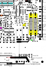
1. Over-current protection is not to enter the protected, and ‘Imax’ set equal to 2500mA, the measuring current reach or more than 2500mA,it will normal suspension of. and traces show normal.
2. When close to the measurement socket next to the LED light, it mearn the circuit into the over-current protection status. it were suspended. The last point of the curve measured values will produce abnormal. and last point on the traces show abnormal.
The curve tracer can measure more than 4A current safely.
Increase the over-current point ,you can replace the green resistor on picture
but the resistor value you need to try.
Or install a tact switch on ProtectSW near the measurement socket. when you press the switch ,the over-current circuit not work,so it can measure no limit current, and board have no protect.(I don't suggest)
Attachments
I will try. Any suggestions for starting values?but the resistor value you need to try.
- Status
- Not open for further replies.
- Home
- Amplifiers
- Solid State
- DIY Curve Tracer for PC