Hi,
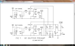
Can I use C100 - C200 1,5uf instead of 1uf and C101 - C201 15uf instead of 10 uf? Because I have these items now. Do they occur a problem in sound ?
Can I use C100 - C200 1,5uf instead of 1uf and C101 - C201 15uf instead of 10 uf? Because I have these items now. Do they occur a problem in sound ?
Cloning the original B1
Has anyone tried to clone the diagrams that Nelson has posted on the PassDIY site ?
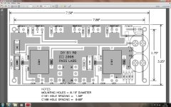
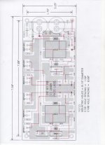
If you look carefully there is a discrepancy between the PCB layout and the schematic.
On the schematic C3 is connected between 0V and Vcc/2.
On the PCB one end of C3 is connected to Vcc.
Which one is right ? Should C3 be across C2 or across D1 ?
Has anyone tried to clone the diagrams that Nelson has posted on the PassDIY site ?
If you look carefully there is a discrepancy between the PCB layout and the schematic.
On the schematic C3 is connected between 0V and Vcc/2.
On the PCB one end of C3 is connected to Vcc.
Which one is right ? Should C3 be across C2 or across D1 ?
Attachments
Last edited:
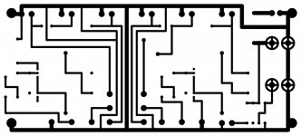
Follow the trace from the bottom of C3 and it is clearly connected to R1, which does not agree with the schematic.
I could see it either helping C3 at HF or quietening the noise from D1.
Both diagrams are from the PASSDIY website.
I could see it either helping C3 at HF or quietening the noise from D1.
Both diagrams are from the PASSDIY website.
Also, does D1 need to be an 1N914 ?
I have bucketfuls of 1N4148 that would probably work here ?
I have bucketfuls of 1N4148 that would probably work here ?
Also, does D1 need to be an 1N914 ?
I have bucketfuls of 1N4148 that would probably work here ?
1N4148 can be used in place of 1N914, however I would use a power diode (1N4001) in that position, I wouldn't trust a signal diode to carry a high current pulse from C2 in a fault condition ie a short across C1.
Lovely. I didn't think that the 1N914 was a critical choice of component.
Thank you.
Next issue is which is right, the PCB or the schematic.
Thank you.
Next issue is which is right, the PCB or the schematic.

It would be more useful to have C3 in parallel with C1, but why not have both. I always put a small cap across an electrolytic irrelevant of whether it's used for coupling or decoupling.
I think I will stick with the version that comes out with the Gerber decode.
At least then I can add more caps if need be.
The mistake would seem to be in the schematic. However, as no-one has spotted it before the schematic obviously works as well.
At least then I can add more caps if need be.
The mistake would seem to be in the schematic. However, as no-one has spotted it before the schematic obviously works as well.
hello.
it looks to me that c3 is connected to V+ and ground (and paralelled to c1).
why is there a red line from r203 to c3 - ground?
it looks to me that c3 is connected to V+ and ground (and paralelled to c1).
why is there a red line from r203 to c3 - ground?
That was my guess as to where the upper copper trace would go. The decode of the gerber files has proved me wrong.
They're just about the same:Also, does D1 need to be an 1N914 ?
I have bucketfuls of 1N4148 that would probably work here ?
1N4148 - Wikipedia, the free encyclopedia
Has anyone got any views about compaing the Aleph P1.7 against the B1.
I've all but given up with the Pumkins. I've got most of the components for either build as a pre for my Aleph 4.
My CD player is almost there with enough drive for the Aleph 4 but not quite.
I like the B1 because of its simplicity.
This weekend I'm going to try the Pumpkins with a single Shuntky. I still cannot get my head around why they sound like "Whooshing", "waves at the beach".
The Whooshing settles down after a while but I still have a minor hum problem. That may be resolved with the single Shuntky.
i would like to purchase one of these units.
Are you not brave enough to try a self-build. The B1 and the P1.7 are fairly simple to build.
True DIYers like myself will start from scratch but kits are available on-line which takes some of the risk out of building them.
nogod - You may buy the B1 circuit board with matching Jfets here - - DIY Order Form
It is a very easy project that sounds absolutely fantastic!
It is a very easy project that sounds absolutely fantastic!
- Home
- Amplifiers
- Pass Labs
- B1 Buffer Preamp