Creative use of redundant positions, nice. With 12V reg straight to the input relays I think there were no erratic denials from the input selection actions in the MEZ.
Before i mount my lvl 1 hot rodded dcb1 into the chassis, i was wondering if it would be better to use the bottom of my chassis (bottom alu sheet measures ~ 350mm x 430mm x 4mm thickness) as the heatsink instead of the heatsinks that i'm using right now. I realize with these heatsinks i can only rest my finger there for at most 5 seconds - it is really quite hot.
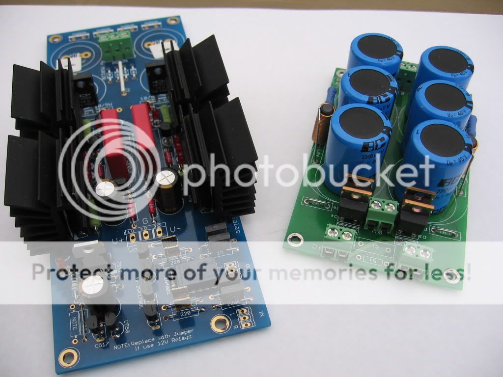
You changed signal resistors to Texas and Caddock? Nice pic. Since the chassis floor is 4mm and the box normal size, better sink them there.
Haha, actually that's not my dcb1. I stole it off someone else here 😛
those vishays are definitely in the pipeline though
those vishays are definitely in the pipeline though
By lvl1, did you mean using 10 ohm resistors for 200 mA?
Before i mount my lvl 1 hot rodded dcb1 into the chassis, i was wondering if it would be better to use the bottom of my chassis (bottom alu sheet measures ~ 350mm x 430mm x 4mm thickness) as the heatsink instead of the heatsinks that i'm using right now. I realize with these heatsinks i can only rest my finger there for at most 5 seconds - it is really quite hot.
Yea, 10 ohm - 200 mA. Will that be a problem?
No, I'm thinking the same thing. My heatsinks is a bit bigger than yours. I don't plan to mount to the chassis and want to make sure it is OK. Now you reported "HOT". Would the DCB1 be stable?
Measure your sinks, if they don't go over 55C, they could make it. Punch ventilation holes on the box under and top of them.
Before i mount my lvl 1 hot rodded dcb1 into the chassis, i was wondering if it would be better to use the bottom of my chassis (bottom alu sheet measures ~ 350mm x 430mm x 4mm thickness) as the heatsink instead of the heatsinks that i'm using right now. I realize with these heatsinks i can only rest my finger there for at most 5 seconds - it is really quite hot.
Would it be a good idea to heatsink the 10 ohm caddocks?
Would it be a good idea to heatsink the 10 ohm caddocks?
Yes, otherwise they are typically 2W's.
Measure your sinks, if they don't go over 55C, they could make it. Punch ventilation holes on the box under and top of them.
That's helpful. 55C is "hot". 🙂
DC offset and Vout are excellent. The sinks are small, will get hotter if you will put it in a closed box. Those Mosfets are tough, but watch that it will be safe. Did you listen at all by now, in what system?
OK, i finished my DCB1, and
Output offset is: Right -1.2 mV and Left -12.5 mV
On Test points i have: -10.21V 197.6mA and +10.28V 224.1mA
On 10R i have: 2.080V 276.2mA and 2.323V 315.7mA
What can be problem ?
OK, i finished my DCB1, and
On 10R i have: 2.080V 276.2mA and 2.323V 315.7mA
What can be problem ?
Those tell me 208mA & 232mA.
Measure again the -12.5mV offset. If its there still, its the only issue and that side will need better JFETS matching.
Those tell me 208mA & 232mA.
Measure again the -12.5mV offset. If its there still, its the only issue and that side will need better JFETS matching.
Thanx !
Measured again, same thing, i put ANOTHER set of "matched" JFETs - and results are diferent but still way diferent what should be - thanx to guys who are selling "matched" quads .. !
Will try again, maybe will solder sockets and test diferent JFETs until i got what i need ...
Better measure them for IDSS than exchanging randomly. Transistor matching
Thanx for advice, i measure IDSS in about 14 JFETs i got - and closest values i got vas 2x 0.71mA and 2x 0.72mA !
I solderd them, and now i have 0.00mA and 0.14mA on output ...
.. actualy, i discover some soldering problem, and after fixing - i got -0.00mA on one channel and 0.02mA on another ...
Good enough ?
Good enough ?
There are no 0.71mA K170BL, you probably got 7.1mA and 7.2mA. The offset you mention is amongst the best reported IF it is mV. There can't be a voltage offset in mA, that's current.
There are no 0.71mA K170BL, you probably got 7.1mA and 7.2mA. The offset you mention is amongst the best reported IF it is mV. There can't be a voltage offset in mA, that's current.
Right, i am too tired this evening, desoldering, soldering, measuring, matching etc ...
JFETs are 2x 7.71mA and 2x7.72mA ...
B U T ...
You are right, i was measuring mA on output - not voltage ...
on Outpur voltage is: -1.3mV and 6.9mV :-(
Is the amp you gonna drive DC input? Or it has a capacitor? The goal is under 5mV offset in order not to be highly multiplied by a DC input amp. Last chance with the JFETS you got, mutually exchange positions in those two associated with the 6.9mV offset. Maybe you luck out and they will fall a bit more, or they simply go higher offset and you put them back as they were.
- Home
- Source & Line
- Analog Line Level
- Salas hotrodded blue DCB1 build