Mister destroyer I fix the Dx Blame Stereo v1.0 too. also I forgot to place a ground trace to the resistor R12. not tested yet....
An externally hosted image should be here but it was not working when we last tested it.
Last edited:
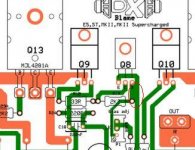
Dx Blame Stereo v1.0
Mister destroyer I fix the Dx Blame Stereo v1.0 too. also I forgot to place a ground trace to the resistor R12. not tested yet.... damn keep forgetting stuff
An externally hosted image should be here but it was not working when we last tested it.
Dx Blame stereo is just an idea not tested and not approved by the schematic designer mister destroyer x, just in case guys, hold your horses.
don't get me wrong... but isn't this just 2 1-channel mkII's attached to eachother with the grounds connected?
Right input to the right part, left to the left... that's it?
Right input to the right part, left to the left... that's it?
yes I just copy one side of the original and placed side by side, and about the grounds can be separated I just connect them via plane, but I can just leave it the way it was like two separated boards, but if I'm not wrong this can work I got to ask destroyer X about it, and yes they are two MKII in the same board I hope you like the idea my friend.
regards
vargasmongo
regards
vargasmongo
Last edited:
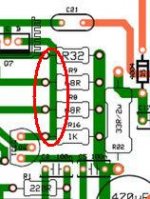
Ok here are the changes but I think was the PDF creator that put the images to close but any way I move the track just in case, thank you so much Alex mm, this take some more studied , I appreciated my friend.
regads,
vargasmongo
regads,
vargasmongo
An externally hosted image should be here but it was not working when we last tested it.
An externally hosted image should be here but it was not working when we last tested it.
Dx Blame Stereo v1.0 track fixed
Ok here are the changes but I think was the PDF creator that put the images to close but any way I move the track just in case, thank you so much Alex mm, this take some more studied , I appreciated my friend.
regads,
vargasmongo
An externally hosted image should be here but it was not working when we last tested it.An externally hosted image should be here but it was not working when we last tested it.
Last edited:
Dx Blame Stereo v1.0 track fixed PDF file
🙄 well I don't know why I can't upload the PDF file what the hell !
🙄 well I don't know why I can't upload the PDF file what the hell !
Pdf has size limit.... and you have not the information the forum cannot do that
Software says anything....just does not upload.
You see the reason why i decided not to support non assembled boards.... this happens a lot.... we, humans, we do mistakes all time long...one after the other, continuously and in a repeated way...this is human.
The worst and most problematic human defect is when guys deny that can make mistakes...these ones are the most dangerous ones... the arrogance made them blind.
And all this go and return, with images published, drives people to panic..they may think we are all idiots...when in the reality we are just humans.
No good.... do not publish step by step procedure please....just fix and publish final work dear Juan...all this process is not good for our image.
Your board is not standard, not supported and have not my appointment....boards for this project are Blue boards Brazilian ones people can find in this home page:
*
Untested boards are no good to be published, also no good to be offered, because can produce a big mess.
Boards should be tested, prior to publish...they should be assembled...then mistakes will appear into the smoke the amplifier will produce..also possible oscilations can be checked.. space in between parts..room to parts... small space in between tracks producing shorts while soldering...all these details appears (only) when we assemble.
regards,
Carlos
Last edited:
Is all good I fallow you my friend humans make mistakes
Software says anything....just does not upload.
You see the reason why i decided not to support non assembled boards.... this happens a lot.... we, humans, we do mistakes all time long...one after the other, continuously and in a repeated way...this is human.
The worst and most problematic human defect is when guys deny that can make mistakes...these ones are the most dangerous ones... the arrogance made them blind.
And all this go and return, with images published, drives people to panic..they may think we are all idiots...when in the reality we are just humans.
No good.... do not publish step by step procedure please....just fix and publish final work dear Juan...all this process is not good for our image.
Your board is not standard, not supported and have not my appointment....boards for this project are Blue boards Brazilian ones people can find in this home page:
*
Untested boards are no good to be published, also no good to be offered, because can produce a big mess.
Boards should be tested, prior to publish...they should be assembled...then mistakes will appear into the smoke the amplifier will produce..also possible oscilations can be checked.. space in between parts..room to parts... small space in between tracks producing shorts while soldering...all these details appears (only) when we assemble.
regards,
Carlos
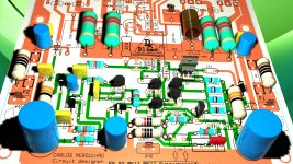
Nice work you are doing Vargas.
This 3D image is very nice.
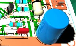
I was watching details...nice!...they made resistor leads shiny having a real metal look .... but shadows are like "man on the moon pictures"..shadows does not make any sense as only electrolytic produces shadows in the correct position (12 hours sunlight).. look that one, the close up picture attached show a stair case shadow when the component is not this way....well.... artistic abstraction they made.... was nice.... also transistor have lost some weight..they are abnormal...too much thin....but i like anyway....it is awesome clear image... detailed image.
We can see mirror effect produced in the electrolytic condenser surface..... nice!
regards,
Carlos
This 3D image is very nice.
I was watching details...nice!...they made resistor leads shiny having a real metal look .... but shadows are like "man on the moon pictures"..shadows does not make any sense as only electrolytic produces shadows in the correct position (12 hours sunlight).. look that one, the close up picture attached show a stair case shadow when the component is not this way....well.... artistic abstraction they made.... was nice.... also transistor have lost some weight..they are abnormal...too much thin....but i like anyway....it is awesome clear image... detailed image.
We can see mirror effect produced in the electrolytic condenser surface..... nice!
regards,
Carlos
Attachments
Last edited:
I am curious to know how long you took to learn how to use the software
and how long you took to create this 3D image.
Usually this spend a lot of time.... watch the software i use to save my time:
http://www.youtube.com/watch?v=TgaYlML5cJQ
regards,
Carlos
and how long you took to create this 3D image.
Usually this spend a lot of time.... watch the software i use to save my time:
http://www.youtube.com/watch?v=TgaYlML5cJQ
regards,
Carlos
Last edited:
That 3d board looks very nice Varga. What program do you use to create such nice art?
Regards
Simon
Regards
Simon
Hi niss_man!
I use 3D Studio max 2010 and all you see is from scratch I have to create models for the components, is fun to do I mean it took about a few years to learn the software xD.
I use 3D Studio max 2010 and all you see is from scratch I have to create models for the components, is fun to do I mean it took about a few years to learn the software xD.
Ahh a proper 3d program. It certainly shows it looks brilliant. I can only use Autocad never learnt 3d studio.
Regards
Simon
Regards
Simon
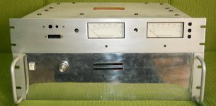
Dx Blame ST and Supercharged built by Newton
He will also build he MKIII Hx.
Here you have a picture and a link to the ST unit playing:
DX ST com VUs - YouTube
regards,
Carlos
He will also build he MKIII Hx.
Here you have a picture and a link to the ST unit playing:
DX ST com VUs - YouTube
regards,
Carlos
Attachments
Last edited:
Here you have a new link to Dx Blame amplifiers data
DX Blame Amplifiers - Carlos Mergulhão
As you know you can have in English and also Portuguese, just click in the flags you will see.
regards,
Carlos
DX Blame Amplifiers - Carlos Mergulhão
As you know you can have in English and also Portuguese, just click in the flags you will see.
regards,
Carlos
- Status
- Not open for further replies.
- Home
- Amplifiers
- Solid State
- Are you ready to face strong emotions?.. Dx Blame MKII and the Supercharged release!