Thank you, I'll give that a try!
I assume since you mentioned the possibility of a pot that the current is minimal <1/2W? Are pots rated for that high a voltage?
Can I try feedback with all modes, UL, Triode, Pentode?
Sorry for all the questions, but I really like tweaking this amp.
Thanks
Glenn
I assume since you mentioned the possibility of a pot that the current is minimal <1/2W? Are pots rated for that high a voltage?
Can I try feedback with all modes, UL, Triode, Pentode?
Sorry for all the questions, but I really like tweaking this amp.
Thanks
Glenn
5AR4 rectifier
Anyone use a 5AR4 rectifier in this build? I'd like to try one to see if I get a little more voltage. Are any changes needed to the rest of the circuit? I assume the 6N1P will also get more than the 200v specified, what does this do to the operating point? I'm using the two red LED bias.
I suppose I should ask if there is any advantage to even raising the B+ on this design? I thought that the advantage to the 5AR4 was the slow warmup time?
Glenn
Very simple...just added a 330k resistor (switchable) between the anodes of the power tube and the driver tube. Adjust amount by varying the resistor value...larger=less feedback, smaller=more feedback. It would be conceivable to use a stereo pot paralleled to a resistor (to keep from going below a minimum value, would not use a pot alone) to have a fully adjustable feedback loop...I plan to do this on my next build...
Are you still using the 6n1p for driver? If you are, with the 330K between anodes, do you still have enough gain to drive the KT88?
I own Jeff's amp now and the answer is yes. In fact, in pentode mode, with or without feedback, the amp gives the most volume compared to the straight UL or triode modes.
Are you still using the 6n1p for driver? If you are, with the 330K between anodes, do you still have enough gain to drive the KT88?
Yes, there are pots rated for 5w and higher.
My B+ runs at 420v and sounds perfect, I think another 20v would make little difference.
The 330k feedback resistor does not apply that much feedback, maybe a 6db cut? Haven't measured it but there is plenty of drive with the 6n1p.
If you use a pot for the feedback be sure to do it in parallel with another resistor...maybe a 250k resistor with a 250k pot in series with a 250k resistor. That would give between 250k-375k in the feedback loop. That's my plan at least.
I own Jeff's amp now and the answer is yes. In fact, in pentode mode, with or without feedback, the amp gives the most volume compared to the straight UL or triode modes.
I agree about the volume, same with mine, but the distortion is higher also.
Glenn
Yes, there are pots rated for 5w and higher.
My B+ runs at 420v and sounds perfect, I think another 20v would make little difference.
The 330k feedback resistor does not apply that much feedback, maybe a 6db cut? Haven't measured it but there is plenty of drive with the 6n1p.
If you use a pot for the feedback be sure to do it in parallel with another resistor...maybe a 250k resistor with a 250k pot in series with a 250k resistor. That would give between 250k-375k in the feedback loop. That's my plan at least.
Mine is around 390-400 depending on line voltage. Are you using the original 5U4G rectifier, or the 5AR4? Just curious.
I just picked-up both 330k &270k 1W resistors today, so I'm going to try the feedback with a switch for now. This way I can cut the feedback in and out to see how it affects the sound.
Thanks for the tips.
Glenn
I like the sound best in pentode with feedback engaged or straight UL. I listen mainly to rock and triode just doesn't seem to have enough drive and snap regardless of distortion.
A very cheap upgrade is replacing the 6N1P with a 6BQ7/6BZ7. You can pick these up for $2 each. I like the 6GU7 a lot too but the gain is to low in any mode but pentode.
A very cheap upgrade is replacing the 6N1P with a 6BQ7/6BZ7. You can pick these up for $2 each. I like the 6GU7 a lot too but the gain is to low in any mode but pentode.
I agree about the volume, same with mine, but the distortion is higher also.
Glenn
What are some good OTs, PTs, and chokes for this amp? I'd really like the OTs to have UL taps, which I guess the Edcors don't offer.
huh?
i thought they all do, if not you can have them make it for you.
i've built one of these withe Edcor trans and i love it.
What are some good OTs, PTs, and chokes for this amp? I'd really like the OTs to have UL taps, which I guess the Edcors don't offer.
i thought they all do, if not you can have them make it for you.
i've built one of these withe Edcor trans and i love it.
Attachments

Oops, you're right. I doesn't say anything in the description but when you scroll down to the wiring scheme it shows the screen connector. Well that's good news, I wanted to use Edcors on my amp because they look cool and they're less expensive. It seems like Edcors are the best choice by far unless you're ready to spend more than $200 per OT.i thought they all do, if not you can have them make it for you.
i've built one of these withe Edcor trans and i love it.
Yes, there are pots rated for 5w and higher.
My B+ runs at 420v and sounds perfect, I think another 20v would make little difference.
The 330k feedback resistor does not apply that much feedback, maybe a 6db cut? Haven't measured it but there is plenty of drive with the 6n1p.
If you use a pot for the feedback be sure to do it in parallel with another resistor...maybe a 250k resistor with a 250k pot in series with a 250k resistor. That would give between 250k-375k in the feedback loop. That's my plan at least.
I was thinking this weekend about the feedback resistor. Doesn't connecting the two anodes together with a resistor change the voltage that the driver runs at (maybe even the KT88)? In addition, doesn't this negate any effects that the LC filter provides for the B+ to the driver tube?
Again, I'm not an Electrical Engineer so maybe I don't fully understand this feedback loop.
Glenn
This is my first go at using PSD2. I'm looking at putting a 5AR4 into the power supply instead of a 5U4-GB. I have a few questions.
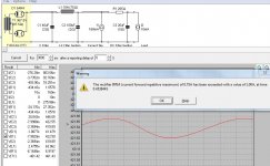
First, did I build this model correctly? I'm still a little shaky on how to model the loads. The first V(I1) is B+, the 160 mA is the draw of the KT88s, and the final RC represents the channel separation as done by Kegger at AK (510R and 10 uF per channel).
Next, PSUD2 throws an error message, complaining that I've exceeded a current capacity of the rectifier. This seems like something that should be a concern. Is it?
Attachments
You need to add an initial delay into the calculation, say 1000ms. I also was getting this error when I first started using the calculator.
Glenn
EDIT: That's about what I got for a B+, right around 420v
Glenn
EDIT: That's about what I got for a B+, right around 420v
I take back what I said about the delay, I don't get that error with 0 delay like you have. Not sure what's going on.
Does the 6N1P really draw 10mA? I thought it was around 7.5mA from all the datasheets I've seen.
Glenn
Does the 6N1P really draw 10mA? I thought it was around 7.5mA from all the datasheets I've seen.
Glenn
It is 7.5, and my previous iterations of the model had that, I just hadn't changed it back. It has very little effect on the model. It certainly doesn't solve the problem I'm having.
Using a reporting delay of 1s causes chaos to occur. The graph becomes solid red and I can't change the range to anything other than 421.655 to 421.685. If I zoom out there are just a vertical lines, and if I zoom out more, the only y value is 421.668. Chaos. So that doesn't work.
What should the transformer resistance be? I just used the built-in calculator based on 350V nominal output at 0.2A, which comes up with 87.5 ohms.
huh, I disabled "soft start" and the error went away. It shows a mighty current spike through the rectifier at start-up, but I guess that's not in accordance with reality, since it takes a few moments for it to heat up.
It is 7.5, and my previous iterations of the model had that, I just hadn't changed it back. It has very little effect on the model. It certainly doesn't solve the problem I'm having.
Using a reporting delay of 1s causes chaos to occur. The graph becomes solid red and I can't change the range to anything other than 421.655 to 421.685. If I zoom out there are just a vertical lines, and if I zoom out more, the only y value is 421.668. Chaos. So that doesn't work.
What should the transformer resistance be? I just used the built-in calculator based on 350V nominal output at 0.2A, which comes up with 87.5 ohms.
Look at the GE 5AR4 datasheet on Frank's Electron Tube Data site. There is a formula on the sheet for calculating the required series resistance value. You might also try reducing the input capacitor to 30uF. The 6N1P RC filter caps only need 10uF. When I built my version of this amp I used LC instead of RC, it provides better filtering. I also initially tried the plate-to-plate feedback. To me it reduces the clarity of the amp, however I am not using pentode mode, too much distortion for my taste. I have mine setup for triode & UL only.
Thanks! Looks like I need two 100 ohm resistors, one for each plate of the 5AR4 to even try this rectifier. I thought I could just swap one in for my 5U4G I now have. I little reading does wonders 🙂
Glenn
Glenn
My transformers shipped yesterday, and all the other parts are sitting on my bench, waiting to be assembled. All, that is, but a chassis.
Can anyone recommend a good chassis for this amp? I was looking at the Hammond chassis at angela and wondering which would be the best size, or if there was a better alternative.
Can anyone recommend a good chassis for this amp? I was looking at the Hammond chassis at angela and wondering which would be the best size, or if there was a better alternative.
- Status
- Not open for further replies.
- Home
- Amplifiers
- Tubes / Valves
- stereo SE kt88 build ... abdellah diyaudioprojects design