It is the SR, as I understand. It has only one gain stage and no MM or MC stage, right?
Yes..... I think........
2n5566 a valid substitute for the 2n5565
Is the 2n5566 a valid substitute for the 2n5565? I have the datasheet in front of me and the only difference I see between the 2n5565 and 2n5566 is the Max differential gate-source voltage. The transconductance values are the same.
http://www.datasheetcatalog.org/datasheet/vishay/70254.pdf
Thanks
Is the 2n5566 a valid substitute for the 2n5565? I have the datasheet in front of me and the only difference I see between the 2n5565 and 2n5566 is the Max differential gate-source voltage. The transconductance values are the same.
http://www.datasheetcatalog.org/datasheet/vishay/70254.pdf
Thanks
Golmund clone
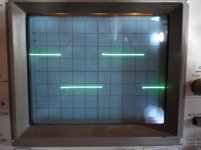
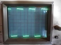
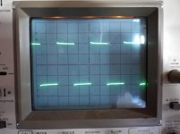
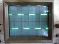
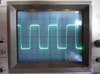
158,159,160,161
1khz-10khz-100khz-200khz
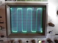
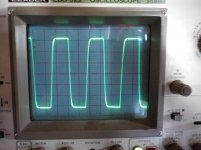
164,165,166,167,168,
1khz-10khz-20khz-100khz-200khz
5volt/div
dc offset +3/-3 mv
158,159,160,161
1khz-10khz-100khz-200khz
164,165,166,167,168,
1khz-10khz-20khz-100khz-200khz
5volt/div
dc offset +3/-3 mv
Attachments
-
 IMGP0158.jpg500.8 KB · Views: 2,025
 -
 IMGP0159.jpg484.7 KB · Views: 1,827
 -
 IMGP0160.jpg498.1 KB · Views: 1,669
 -
 IMGP0161.jpg498.7 KB · Views: 1,548
 -
 IMGP0163.jpg593 KB · Views: 1,597
 -
 IMGP0164.jpg506.2 KB · Views: 545
 -
 IMGP0165.jpg478 KB · Views: 190
 -
 IMGP0166.jpg498.6 KB · Views: 202
 -
 IMGP0167.jpg507.1 KB · Views: 215
 -
 IMGP0168.jpg505.7 KB · Views: 258
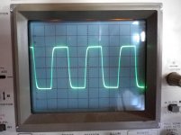
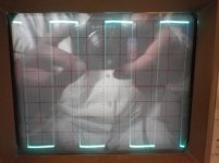
So, what is the conclusion for these nikosokey ? I know that there is a signal applied to the input of the amp and the output is measured through the CRO. But I don't know what those CRO graphs say. Could someone tell me what the result is?
158,159,160,161
1khz-10khz-100khz-200khz
164,165,166,167,168,
1khz-10khz-20khz-100khz-200khz
5volt/div
dc offset +3/-3 mv
Have you checked the compensation on your probes to be sure that the probes are not introducing something? Forgive my thought if you have, just checking...
and check the input signal using a spare scope channel, so that you can compare input to output.Have you checked the compensation on your probes to be sure that the probes are not introducing something? ............
Krisf-AndrewT
Is twenty years old oscilloscope and I have only one probe.
(there is economic crisis)
I will try with two next days.
Waveforms show that the amplifier not doing badly
I have to convert the transistor bss71,74 to output transistors with 150 ohms resistance emitter (small amp) until come the output transistors.
Hi,
Just out of curiosity, you did not change the compensation?
Also, if times allows, just for curiosity, could try this with 10K in parallel with 1nF load, this would give an idea how the Goldmund Preamps will do, especially with a reduced frequency compensation...
Ciao T
I have to convert the transistor bss71,74 to output transistors with 150 ohms resistance emitter (small amp) until come the output transistors.
Just out of curiosity, you did not change the compensation?
Also, if times allows, just for curiosity, could try this with 10K in parallel with 1nF load, this would give an idea how the Goldmund Preamps will do, especially with a reduced frequency compensation...
Ciao T
ThorstenL
((Just out of curiosity, you did not change the compensation?))
I have not made any changes about compensation.
((Just out of curiosity, you did not change the compensation?))
I have not made any changes about compensation.
Hi,
Good to know. With a Goldmund style 330 Ohm build out resistor this should allow the preamp circuit to be de-compensated to the same levels as the Poweramp.
More speed, more better (I come from Germany where it IS FUN to own a fast car)...
Ciao T
ThorstenL
((Just out of curiosity, you did not change the compensation?))
I have not made any changes about compensation.
Good to know. With a Goldmund style 330 Ohm build out resistor this should allow the preamp circuit to be de-compensated to the same levels as the Poweramp.
More speed, more better (I come from Germany where it IS FUN to own a fast car)...
Ciao T
Hi,
Very nice results!
I've estiminated the slew rate from the 200 kHz oscilloscope graph of about 60V/us!
But these measurements are made without a load, are they?
If you don't mind, can you make a test with 100kHz or 200 kHz but with an 1 Ohm resistor and a 1 uF capacitor in series as load and zoom into the falling slope, how quick/slow it falls. This would show the ability of this amp to drive capacitive loads. If the slew rate wouldn't decrease that much, I could use this amp to drive my piezo-speakers, which behaves almost like a 1 ohm resistor with a 1uF resistor in series ...
Don't worry about the resistor. A 1.5 W would be absolutely sufficient, sience there isn't flowing that mich current, due to the capacitor in series (~ 50 mA).
O.
158,159,160,161
1khz-10khz-100khz-200khz
164,165,166,167,168,
1khz-10khz-20khz-100khz-200khz
5volt/div
dc offset +3/-3 mv
Very nice results!
I've estiminated the slew rate from the 200 kHz oscilloscope graph of about 60V/us!
But these measurements are made without a load, are they?
If you don't mind, can you make a test with 100kHz or 200 kHz but with an 1 Ohm resistor and a 1 uF capacitor in series as load and zoom into the falling slope, how quick/slow it falls. This would show the ability of this amp to drive capacitive loads. If the slew rate wouldn't decrease that much, I could use this amp to drive my piezo-speakers, which behaves almost like a 1 ohm resistor with a 1uF resistor in series ...
Don't worry about the resistor. A 1.5 W would be absolutely sufficient, sience there isn't flowing that mich current, due to the capacitor in series (~ 50 mA).
O.
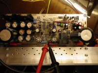
Golmund clone
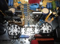
Dual CCS with MJE340G On Semi unmatched
VAS Stage with MJE350G On Semi unmatched
DC Offset very very stable 1-2 mv
R1=3.159
R2=3.158
R17=2.932
R18=2.932
R17=2.133
R14=2.662 Positive probe on positive rail and negative probe on emmiter T7
R15=2.662 Positive probe on positive rail and negative probe on emmiter T8
R22 and R19 = 8,2KΩ Τotal
C5,C6,C7,C3=4,7 pf
Foto 20Khz -200khz -100khz 5V/div
Attachments


Last edited:
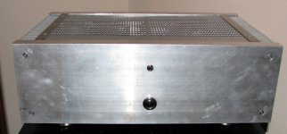
I just love the heatsinks.
Binding with a couple of turns of copper wire would be better than that black band.
Binding with a couple of turns of copper wire would be better than that black band.
nikosokey said:Dual CCS with MJE340G On Semi unmatched
VAS Stage with MJE350G On Semi unmatched
DC Offset very very stable 1-2 mv
Can you kindly post a detail of this and where to add ? Starting to plan for a new version of pcb and might as well add this. Stan's (sng001) thermal coupling of the T7,8,9,10 s are under consideration also.
Can you kindly post a detail of this and where to add ? Starting to plan for a new version of pcb and might as well add this. Stan's (sng001) thermal coupling of the T7,8,9,10 s are under consideration also.
That sounds great! When are you planning to start the group buy on this new PCB layout? Hopefully you have a soldermask included this time. Sign me in. 🙂
Hi,
Solder mask is for certain. It is missing last time solely because the original starter of this thread doesn't want it and I had to respect his demand. Now he is gone (I don't mean that "GONE"), I will include that which is, hopefully, most members would like.
But I doubt if I would do it as group buy again from last experience which was pretty awful.
BP
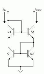
new schematic
.... I have redraw schematic acording nikosokey implementation 🙂 home made case .....
Alex.
.... I have redraw schematic acording nikosokey implementation 🙂 home made case .....
Alex.
Attachments

Last edited:
- Home
- Amplifiers
- Solid State
- The Very Best Amplifier I Have Ever Heard!!!!