It looks familiar 😀
You are just listening to the junctions of the MPSA92/42 through the laterals , that is the original's "signature".
OS
Interesting conclution ostripper.
The current GM models seems to use FZT857/957 instead of the MPSAs according to an other tread in this forum. Is this correct? The FZT857/957 have a COB of 20-25 pF!
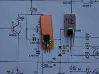
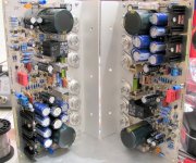
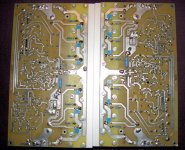
I have made the following PCB to fit the Yamaha case.
Attached is some pictures.
What are the standing PCB sticks attached to those TO-92s? Heatsink/miller compensation combined?
- keantoken
Really , try the real Ksa/c 1381/3503's , I am listening to them now as my VAS.Hi Stanley,
I have some if you would like to try them. You can pick them up if you live on my side of Sydney, or PM your postal address. I think they are E versions.
regards
NOTHING can compare to the 125V/us slew and how this equates to the final sonic signature. fairchild/mouser is the source , most of my pairs are 143- 150 Hfe ... all of them (E gain group).Very pleased with the semi's 🙂 .
OS
Last edited:
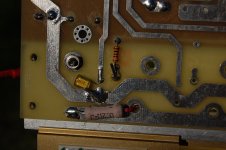
What are the standing PCB sticks attached to those TO-92s? Heatsink/miller compensation combined?
- keantoken
Hi KT,
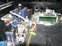
The standing PCB stick are just heatsink as superglue sticks very well to polished copper & FR4 is much easier to work with. I imagine that a Miller capacitor can be added if one is needed. There is a flaw with this heatsink - the pins on the TO92 can break quite easily.
The VAS on the GM clone is running quite hot, I used a 60mm (W) x 50mm (H) x 3mm alu heatsink and it is running at 20C above the ambient.
Cheers, Stanley
Attachments
Interesting conclution ostripper.
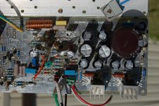
The current GM models seems to use FZT857/957 instead of the MPSAs according to an other tread in this forum. Is this correct? The FZT857/957 have a COB of 20-25 pF!
Hi tommy1000,
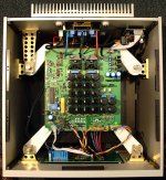
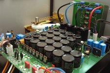
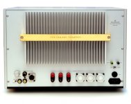
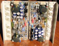
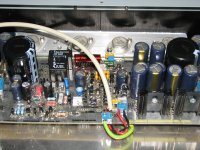
I also read the other thread, the VAS stage of the Telos 2500 is surprisingly similar to Mimesis 9. The FZT857/957 are SMT devices so that they can be potted together with the IPS to form a single thermal block - that would help to solve the drifting offset problem.
BTW, I found some internal pictures of the Telos 2500.
Cheers, Stanley
Attachments
Last edited:
VAS choice
Hi OS,
I have tried BF469/470 & 2SB1109/D1609 & 2SA1538/3953 and they all sound a bit different, although the difference is quite subtle.
Philips BF469/470 - better bass & loss a bit in details
Hitachi 2SB1109/D1609 - very close to MPSA, slightly warmer bass
Sanyo 2SA1538/3953 - very clear treble, less bass.
I like the MPSA more than the others, I may have to make another board for the MPSA VAS.
Cheers, Stanley
Really , try the real Ksa/c 1381/3503's , I am listening to them now as my VAS.
NOTHING can compare to the 125V/us slew and how this equates to the final sonic signature. fairchild/mouser is the source , most of my pairs are 143- 150 Hfe ... all of them (E gain group).Very pleased with the semi's 🙂 .
OS
Hi OS,
I have tried BF469/470 & 2SB1109/D1609 & 2SA1538/3953 and they all sound a bit different, although the difference is quite subtle.
Philips BF469/470 - better bass & loss a bit in details
Hitachi 2SB1109/D1609 - very close to MPSA, slightly warmer bass
Sanyo 2SA1538/3953 - very clear treble, less bass.
I like the MPSA more than the others, I may have to make another board for the MPSA VAS.
Cheers, Stanley
Hi Sng,
swapping device/s at the same current setting is not a fair comparison.
Each device should have it's operating condition optimised to suit the characteristics of the device.
eg. the MPSA may perform well with Ic~300uA. Some of the alternatives may work better at 100uA or 800uA or some other value that should be determined.
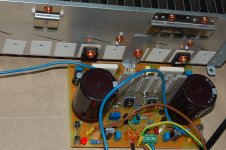
Second channel populated
Hi all ,
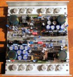
I managed to finish, and the second channel, I started one channel, and I can easily adjust the offset to 1 mV. There is a difference between voltages 2 -3 V at rail drivers . I'll stick it into the case then do all the tests with audio generator and oscilloscope. I like the sound, but I had no real speakers when testing from a friend of mine 🙂
Alex .
Hi all ,
I managed to finish, and the second channel, I started one channel, and I can easily adjust the offset to 1 mV. There is a difference between voltages 2 -3 V at rail drivers . I'll stick it into the case then do all the tests with audio generator and oscilloscope. I like the sound, but I had no real speakers when testing from a friend of mine 🙂
Alex .
Attachments
Farl
Congratulations with your Golmund clone.
What about some pictures, Farl?
Who is the next one out with their building results??
Eivind Stillingen
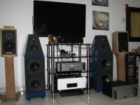
Some pictures....
Attachments
Goldmund builders,
You guys now so well advanced with the Goldmund amplifier.
We will greatly appreciate if you all have finished the Goldmund clone, to create a new parts list to cover other builders to have also there benefit.
Because some of the parts are that difficult to get, would you all together create for us a new parts list with the components “that you have used”.
And mention where you get the difficult to get parts ordered.
What also is useful to create a simple up to date "PDF" file with the things to lookout for if there are errors in the schema.
Thanks, and keep us informed,
Rudy
Note, sorry that I wrote this for the second time
For those who might want to help in updating BOM list, I have upload an excel (windows) file, hopefully making work easier.
FileFactory Folder view - gm-work
bom-GM-up.xls
FileFactory Folder view - gm-work
bom-GM-up.xls
aarrgh! there are also few links posted in the past that state the final schema and bom of this project. im cofused!
Last edited:
so guys ; till now how many goldmund clones are successful? has anyone tried to put the original mosfets in their clone that goldmund used? (rather than mosfets being xpensive) to get that real juice from them?
GM Mimesis 3 clone part list
Hi all,
I have built the Mimesis 3 using the AlexMM board, the amp sounds very good. I want to share the parts list that I used.
Please note that I am building the Mimesis 3 clone using 40V AC transformer & I only ordered 63V capacitors, so substitute them with 100V capacitors if you are building Mimesis 9.2 clone.
The most difficult bits is to find the right high-wattage ressistors - I chose Metal-Oxide type if that is available. I used carbon composite type for R20, R23 & the 100-ohm gate stoppers.
For the output MOSFETs, I used Renesis 2SJ162/K1058.
For T3 & T5 on the Protection circuit, I used 2N5551 instead of the BC449.
The attached file is not the complete parts list as I got some parts in my parts bin. I included the Mouser part number in the MS Excel spreadsheet, which can be used as a starting point to compile the complete part list.
Cheers, Stanley
Attachments
please can somebody post (or pm me) the schematics of mimesis 9? i am interested to build this stereo amp and hear them. also i think it matches the power requirements for my speakers... thankyou...
alex mm, I think those schematics are of mimesis9.2 (monoblock amp).
But i want the schematics of mimesis 9 only (the stereo amp)......
because i want to have stereo amp.... I wonder if it is available or not.........because i haven't found one....
Of course, no doubt that mimesis 9.2 x2 can be made for stereo. but i don't need that plenty of power. mimesis 9 will be great for me.
BTW, thanks for post alex mm....
Kindly post if you find or have mimesis 9(stereo amp version) schematics......
Thank you......

- Home
- Amplifiers
- Solid State
- The Very Best Amplifier I Have Ever Heard!!!!