I'm in for one, please let me know how can connect it?
Felipe, I will contact you when I have the circuit ready!
Any preferences for an input cap? I'm using a 0.1uF Russian silver mica. I also have the Russian teflon ones of various kinds I could try - thinking FT-2.
Andy
The Russian Telflons (фтоуропласт) are certainly worth trying, I use the К72П-6 56nF/500V which are easy to find. The 1.25 inch pipe cutter from Rapid Electronics can fetch the steel case off them, when you get the hang of it (buy an extra cap to practice)
Rapid Electronics - Pipe Cutter 3-32mm
My other favourite is a sleeper - the LCR components PC/HV/S high quality industrial polypropylene. For coupling, there may be a better cap, but I have not found one. 1kV or 1.5kV rating, too. These can be used from preamps all the way up to Tesla coils - they are so well built.
LCR COMPONENTS|PC/HV/S/WF 100NF 1KV|CAPACITOR, 100NF, 1000V | Farnell United Kingdom
Rod -
I tried out two different supplies to your boards - a Thurby Thandar bench supply and a choke input supply. Both sound different - still experimenting.
What's your guess at the best supply to precede your boards? Seems like differences are audible.
andy
I tried out two different supplies to your boards - a Thurby Thandar bench supply and a choke input supply. Both sound different - still experimenting.
What's your guess at the best supply to precede your boards? Seems like differences are audible.
andy
Rod -
I tried out two different supplies to your boards - a Thurby Thandar bench supply and a choke input supply. Both sound different - still experimenting.
What's your guess at the best supply to precede your boards? Seems like differences are audible.
andy
I don´t know Rod´s circuit, but perhaps it´s a good idea to use an Ultra Low ESR PSU like i use it for the Salas shunt´s in my DAC...🙄
Hi Andy,
Before drawing conclusions, it is best to get an understanding what your implementations of the PSUs actually do. Choke input is not just equal to any choke input. Hook up a scope and check AC voltages across the secondary of the transformer and right after the rectifier bridge. Especially with choke input you can have some nasty spikes there which can creep into the circuit. Sometimes it is a good idea to tame these with a small cap in front of the choke. Try something like 47uF and move upwards until the spikes with rough edges dissappear.
Best regards ... Thomas
I tried out two different supplies to your boards - a Thurby Thandar bench supply and a choke input supply. Both sound different - still experimenting.
What's your guess at the best supply to precede your boards? Seems like differences are audible.
Before drawing conclusions, it is best to get an understanding what your implementations of the PSUs actually do. Choke input is not just equal to any choke input. Hook up a scope and check AC voltages across the secondary of the transformer and right after the rectifier bridge. Especially with choke input you can have some nasty spikes there which can creep into the circuit. Sometimes it is a good idea to tame these with a small cap in front of the choke. Try something like 47uF and move upwards until the spikes with rough edges dissappear.
Best regards ... Thomas
Hi Andy,
Before drawing conclusions, it is best to get an understanding what your implementations of the PSUs actually do. Choke input is not just equal to any choke input. Hook up a scope and check AC voltages across the secondary of the transformer and right after the rectifier bridge. Especially with choke input you can have some nasty spikes there which can creep into the circuit. Sometimes it is a good idea to tame these with a small cap in front of the choke. Try something like 47uF and move upwards until the spikes with rough edges dissappear.
Best regards ... Thomas
Andy, this is good advice from Thomas.
Choke input means a big reduction in the peak current into the reservoir caps. Reducing this current can improve the sound of other parts of the audio system connected to the same mains supply.
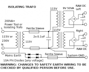
The type of mains trafo is also important. split bobbin type reduces noise transfer from the mains (compared to toroidal or overwound types), and high quality trafos with an Electrostatic screen can be even better still. My preference is to use an isolating transformer, and an HF barrier in the safety earth (Sadly, safety earth can transmit some troublesome noise): the drawing shows a suggestion for connecting it.
Attachments
Hi Andy,
I never liked battery bias. And I also never 'settled' on filament bias 😛
In most of my designs I use regular cathode bias with the ultrapath topology. I only use filament bias if all other aspects in the design are already on the best possible level and when the heat generated in the filament bias resistor is of no concern. While the latter is not much of an issue in a 26 stage, the heat dissipation can be excessive with 801As.
Best regards ... Thomas
What did you think of grid bias with battery, before settling on filament bias?
I never liked battery bias. And I also never 'settled' on filament bias 😛
In most of my designs I use regular cathode bias with the ultrapath topology. I only use filament bias if all other aspects in the design are already on the best possible level and when the heat generated in the filament bias resistor is of no concern. While the latter is not much of an issue in a 26 stage, the heat dissipation can be excessive with 801As.
Best regards ... Thomas
Has anybody compared different battery types in PP3 9v?
- alkaline
- lithium
- zinc carbon
- zinc chloride
- other
Would there be any difference in sound?
Andy
- alkaline
- lithium
- zinc carbon
- zinc chloride
- other
Would there be any difference in sound?
Andy
Hi!
I fully agree with Rod on this. Using cheap power transformers is cost saving in the wrong place. Especially if the power supply changes seem to have a big impact on the sound, this could be due to a poor power trannie. I settled on power transformers with two independent screen windings. In fact the screens are not windings, but electrostatic screens made with foils. Also the core material of the power transformer has an impact.
Best regards ... Thomas
The type of mains trafo is also important. split bobbin type reduces noise transfer from the mains (compared to toroidal or overwound types), and high quality trafos with an Electrostatic screen can be even better still.
I fully agree with Rod on this. Using cheap power transformers is cost saving in the wrong place. Especially if the power supply changes seem to have a big impact on the sound, this could be due to a poor power trannie. I settled on power transformers with two independent screen windings. In fact the screens are not windings, but electrostatic screens made with foils. Also the core material of the power transformer has an impact.
Best regards ... Thomas
I found that a say 2uf film cap sounded better than smaller say .5uf Vitamin Q on Duracells. I have not tried any other caps, however a cap did sound better than no cap."
Found this comment. Is there any benefit from bypassing a grid battery?
Andy
Found this comment. Is there any benefit from bypassing a grid battery?
Andy
DIYers that are enthusiastic about battery bias usually have favourite brands of alkaline batteries, and perform noise measurements to compare them. Using large value caps across a 9V alkaline suggests they are not quiet enough.
Other battery chemistry, especially lead-acid gel cell, and NiMH are known to be too noisy. There's measurements available on this site, to be searched out.
Other battery chemistry, especially lead-acid gel cell, and NiMH are known to be too noisy. There's measurements available on this site, to be searched out.
What about LiFePO4 battery? Supposed to be the leading edge technology nowadays.
Internal resistance down to few mOhms, probably bypassing caps not required.
Cells are 3.6 V (nominal) each and to charge them tiny smd ICs (3x3 mm!) such as MCP73123 can be used with minumum external parts.
Internal resistance down to few mOhms, probably bypassing caps not required.
Cells are 3.6 V (nominal) each and to charge them tiny smd ICs (3x3 mm!) such as MCP73123 can be used with minumum external parts.
What about LiFePO4 battery? Supposed to be the leading edge technology nowadays.
Internal resistance down to few mOhms, probably bypassing caps not required.
Cells are 3.6 V (nominal) each and to charge them tiny smd ICs (3x3 mm!) such as MCP73123 can be used with minumum external parts.
Good idea, suggested circuit schematic for charger?
IC Manufacturer's application note. http://ww1.microchip.com/downloads/en/AppNotes/01276a.pdf
Two caps, two resistors, one led + one cheap wall mart p.s. (you might already have a suitable one around)
Two caps, two resistors, one led + one cheap wall mart p.s. (you might already have a suitable one around)
You cannot, of course, but you can eventually chose a different operating point based on -7.2V (2 cells) or -10.8V (3 cells) bias.
I'rather go with -7.2V and with two cells in series you can use the MPC73223 chip instead
I'rather go with -7.2V and with two cells in series you can use the MPC73223 chip instead
Good idea, suggested circuit schematic for charger?
For the application discussed here, you have probaly trashed the preamp and built a new one before you will have to recharge the batteries.😉 I suppose that the shelf life of this type of batteries are even better than with lithium batteries. Since the grid draws extremely little current, I would expect a LiFePO4 to last many years in a linestage.
Last edited:
- Home
- Amplifiers
- Tubes / Valves
- #26 pre amp