Hello Apex,
I want to get started building the B500 amplifier. I hope you can post the 'APEXaudio B500 PCB.pdf' in mirrored image so that I can use it for making the PCB using the laser toner procedure. If it ain't too much to ask, can you put two mirrored pcb layouts in one page in the other page has two unmirrored pcb layouts?
Thank you so much!
Thank you so much!
Hi andrew,
I am on the way of making b500, but have some questions
what are a and b on pcb,
does it require any other power supply other than 90v .
Point A and B are basically used when you want to use the amp in bridge mode. You may need to have two B500 amplifier circuits to do this. I believe there’s a wiring diagram somewhere posted here.
Hello Apex,
Sir, can I replace MJE340 and MJE15032 with 2SC4793 as well as MJE350 and MJE15033 with 2SA1837?
MJE15032 with BD243C?
MJE15033 with BD244C?
I can't seem to find the MJE15032 and 33 here on our locality. I will be drilling the holes and place all the parts later.
Thanks!
Sir, can I replace MJE340 and MJE15032 with 2SC4793 as well as MJE350 and MJE15033 with 2SA1837?
MJE15032 with BD243C?
MJE15033 with BD244C?
I can't seem to find the MJE15032 and 33 here on our locality. I will be drilling the holes and place all the parts later.
Thanks!
Attachments
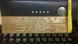
hi, blueice23 how did u made the pcb? lazer toner transfer method or screen printing?
Last edited:
Hello Apex,
Sir, can I replace MJE340 and MJE15032 with 2SC4793 as well as MJE350 and MJE15033 with 2SA1837?
MJE15032 with BD243C?
MJE15033 with BD244C?
I can't seem to find the MJE15032 and 33 here on our locality. I will be drilling the holes and place all the parts later.
Thanks!
Yes you can replace MJE340 and MJE15032 with 2SC4793 as well as MJE350 and MJE15033 with 2SA1837.
BD243C/244C can't be use for B500.
Regards
hi, blueice23 how did u made the pcb? lazer toner transfer method or screen printing?
Hi Nazirdigi,
Yes, it was indeed made with laser toner transfer method. I will make a stencil soon so that i can print it using silkscreen for better quality.
Cheers,
Blueice23
Hello Apex,
Sir, what is the recommended supply voltage for the B500 amp with step driver?
Can I use +/- 110Vdc for the +/- HV rails and +/- 85Vdc for +/- MV? If so, I will rewind a transformer of 2 x 60Vac and add 2 x 18Vac to get 78Vac.
60Vac * 1.414 = 84.84 Vdc @ 12A
78Vac * 1.414 = 110.292 Vdc @ 12A
core size is at 2" x 4"
Thanks!
apex b500...
thank u sir apex....🙂
thank u sir apex....🙂
Attachments
-
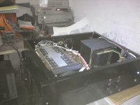 Photo0620.jpg614.5 KB · Views: 1,820
 -
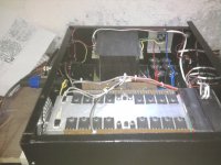 Photo0619.jpg708.5 KB · Views: 1,522
 -
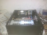 Photo0618.jpg706.5 KB · Views: 1,316
 -
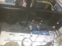 Photo0614.jpg752.7 KB · Views: 352
 -
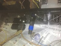 Photo0615.jpg956.4 KB · Views: 424
 -
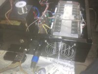 Photo0616.jpg629.7 KB · Views: 1,167
 -
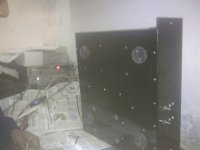 Photo0613.jpg510 KB · Views: 314
 -
 Photo0612.jpg622.3 KB · Views: 391
 -
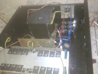 Photo0611.jpg704.8 KB · Views: 423
 -
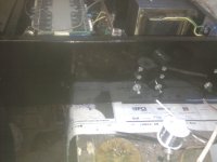 Photo0610.jpg567.7 KB · Views: 347
Hello Apex,
Sir, what is the recommended supply voltage for the B500 amp with step driver?
Can I use +/- 110Vdc for the +/- HV rails and +/- 85Vdc for +/- MV? If so, I will rewind a transformer of 2 x 60Vac and add 2 x 18Vac to get 78Vac.
60Vac * 1.414 = 84.84 Vdc @ 12A
78Vac * 1.414 = 110.292 Vdc @ 12A
core size is at 2" x 4"
Thanks!
I sugggest +/-110V for HV and +/-55V for MV, you can use +/-85V for MV but only for 8R load.
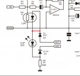
IS THIS CORRECT?Add LED in series with LED integrited in NSL32, and you have clip/limit indication.
Regards
Attachments
hello sir....
sound is boooom boooom
and verry HI-FI
thank u sir apex
Clear and loud

Yes, if you don't want use limiter.
IS THIS CORRECT?
WHITHOUT CLIPPING.
WHAT IS LED DOING?
Attachments

IS THIS CORRECT?
WHITHOUT CLIPPING.
WHAT IS LED DOING?
LED will blink at high power🙂
LED will blink at high power🙂
THANK U VERY MUCH FOR YOUR COPERATION.
Hello Apex,
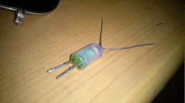
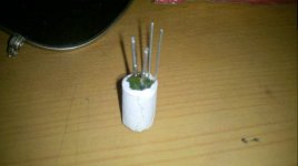
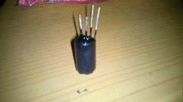
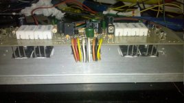
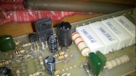
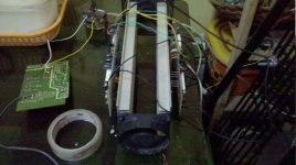
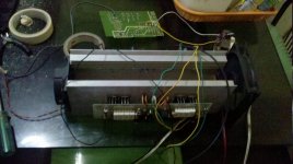
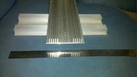
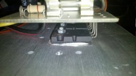
Sir, here are the pictures of the B500 I made. I have also attached the LED/LDR assembly as well as the ML3 tone control PCB ready for drilling.
I have used the following:
1. +/- 50Vdc @ 6Amp for testing
2. Opamp LM358.
3. Pre-Driver transistors are MJE340 / 2SA1837
4. Driver transistors are 2SA940 / 2SC2073
5. Output transistors are 2SA1943 / 2SC5200
6. Manex 8" sub rated 200 @ 8 Ohms.
7. DC offset voltage is @ negative 0.05miliVolts with and without speakers (positive test lead is connected to the speaker output and the negative test lead is connected to the ground).
Is this normal to have negative DC offset for the B500 amp? My previous amplifier designs have positive DC offset.
To what value I may need to change the R24/R25? I have used 2.2K @ 2w and I have noticed that it's hot. Can I change the value to 6.8K @ 5W for +/-85Vdc voltage rails?
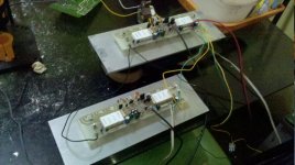
Both channels having two pairs of output transistors each were playing at full volume (no tone controls yet) from 07:00 A.M. to 05:00 P.M with minimal heat. Great sounding amp, Loud and Clear! I will bridge the amps later and upgrade it to have the step driver circuit.
Thank you so much for the assistance and for sharing the B500!
Cheers,
Blueice23 😎 😎 😎
Sir, here are the pictures of the B500 I made. I have also attached the LED/LDR assembly as well as the ML3 tone control PCB ready for drilling.
I have used the following:
1. +/- 50Vdc @ 6Amp for testing
2. Opamp LM358.
3. Pre-Driver transistors are MJE340 / 2SA1837
4. Driver transistors are 2SA940 / 2SC2073
5. Output transistors are 2SA1943 / 2SC5200
6. Manex 8" sub rated 200 @ 8 Ohms.
7. DC offset voltage is @ negative 0.05miliVolts with and without speakers (positive test lead is connected to the speaker output and the negative test lead is connected to the ground).
Is this normal to have negative DC offset for the B500 amp? My previous amplifier designs have positive DC offset.
To what value I may need to change the R24/R25? I have used 2.2K @ 2w and I have noticed that it's hot. Can I change the value to 6.8K @ 5W for +/-85Vdc voltage rails?
Both channels having two pairs of output transistors each were playing at full volume (no tone controls yet) from 07:00 A.M. to 05:00 P.M with minimal heat. Great sounding amp, Loud and Clear! I will bridge the amps later and upgrade it to have the step driver circuit.
Thank you so much for the assistance and for sharing the B500!
Cheers,
Blueice23 😎 😎 😎
Attachments
-
 2011-01-30_16-10-28_146.jpg79.2 KB · Views: 1,602
 -
 2011-01-30_16-17-55_864.jpg73.6 KB · Views: 1,528
 -
 2011-01-30_16-24-02_682.jpg82.4 KB · Views: 1,489
 -
 2011-01-31_15-20-09_489.jpg122.3 KB · Views: 575
 -
 2011-01-30_19-41-51_447.jpg113.4 KB · Views: 628
 -
 2011-01-30_16-32-39_11.jpg102.8 KB · Views: 661
 -
 2011-01-31_15-40-08_186.jpg117.4 KB · Views: 549
 -
 2011-01-31_15-40-22_242.jpg118.4 KB · Views: 460
 -
 2011-01-30_21-47-47_38.jpg88.3 KB · Views: 467
 -
 2011-01-30_19-43-18_119.jpg85.2 KB · Views: 478
Hello Apex,
Sir, here are the pictures of the B500 I made. I have also attached the LED/LDR assembly as well as the ML3 tone control PCB ready for drilling.
I have used the following:
1. +/- 50Vdc @ 6Amp for testing
2. Opamp LM358.
3. Pre-Driver transistors are MJE340 / 2SA1837
4. Driver transistors are 2SA940 / 2SC2073
5. Output transistors are 2SA1943 / 2SC5200
6. Manex 8" sub rated 200 @ 8 Ohms.
7. DC offset voltage is @ negative 0.05miliVolts with and without speakers (positive test lead is connected to the speaker output and the negative test lead is connected to the ground).
Is this normal to have negative DC offset for the B500 amp? My previous amplifier designs have positive DC offset.
To what value I may need to change the R24/R25? I have used 2.2K @ 2w and I have noticed that it's hot. Can I change the value to 6.8K @ 5W for +/-85Vdc voltage rails?
Both channels having two pairs of output transistors each were playing at full volume (no tone controls yet) from 07:00 A.M. to 05:00 P.M with minimal heat. Great sounding amp, Loud and Clear! I will bridge the amps later and upgrade it to have the step driver circuit.
Thank you so much for the assistance and for sharing the B500!
Cheers,
Blueice23 😎 😎 😎
Nice work, small offset positive or negative is normal.
I suggest to use red LED, did you measure ldr resistance whan led off and on?
2k2/2W must be hot, for +/-85V use 3k9/5W or two 8k2/2W in parallel.
Thanks for shareing picture and expirience with B500.
Regards
- Home
- Amplifiers
- Solid State
- 500W PA amplifier with Limiter