Josip,
It is cascoded, but the voltage on 2N5565 is about 30V. If ou want to use J309 you need to change the resistors ratio for cascode.
dado
It is cascoded, but the voltage on 2N5565 is about 30V. If ou want to use J309 you need to change the resistors ratio for cascode.
dado
I thought it was cascoded but I am not a expert, so I ask you. Sorry if I am annoying
replace lower cascode bias resistor from 33K to -say-25K and you'll be good for J309 25V max
it will work even with original 33K value , up to +/-63V PSU
problem is in input stage - where low Idss and low xconductance Jfets are used ;
J309 have almost dozen times higher xconductance and that will influence OLG ....
try with even larger source resistors , instead 75R - 100 or 120 for start
in case of instability - increase them further
anyway - for cascode biasing - increase 51K to 68K , decrease 33K to 22K
Last edited:
I ask because, i plan to build Goldmund V3. So can I put J309 without changing voltage in front stage?
I ask because, i plan to build Goldmund V3. So can I put J309 without changing voltage in front stage?
gimme schmtc and I'll tell you
I think schematic from post #19 is relevant for cascode resistor values
anyway - 40V , resistors 51K and 33 K - voltage at cascode bases is 40vx33/51=25V
too much for J309/J310 ......
let's say that proper voltage for J309/J310 is similar as to 2SK170 , somewhere around 12-15V , with proper current
so - my advice will be the same , regarding values of these resistors - decrease lower one , increase upper one.
even if I didn't make thorough analysis of these Goldmund schematics - everything I saw in schematic itself , and in process of starting cloning adventure ....... I'll stay away from it 😉
Thanks, once again
Just curiosity, Bad schematic, or something else?
OP attitude - which isn't so important , but results in numerous mistakes and wrong claims ; so - you simply cannot trust in any value , without detailed analysis ; having that amount of work involved in schematic , which also demands adequate level of knowledge - it's certainly easier to construct one of your own ....
besides that - whenever I see mediocre current in any stage in amp , I'm running away ....

Another I presume rather stupid question. Does lateral fets matched the same as Hexfet.
And how close should they be matched (I know the closer the better)
And how close should they be matched (I know the closer the better)
laterals have smaller Ugs spread then hexfets , but anyway you need to match them
at least on Iq , for planned amp
say that matching them to 10mV of Ugs is more than good enough
you can buy 2SJ201/2SK1530 from Zhoufang and use just one pair for channel if you are not using it in current hungry application (it have double xconductance comparing to buz ) or buy matched pairs of same from him - if going current hungry route
R22 in that schmtc must be made of resistor and pot in series
I just got a stack of exicon lateral mosfets both TO3 and TO247 and the level of matching is excellent.
I have found with IRFP240/9240 there is quite a large spread of Vgs and you need to buy many more to get good matching. Not so with these laterals.
I will say though it is hard to get matching between N and P for the laterals.
The N's tend to all turn on with Vgs of around 0.18V while the P's turn on around Vgs of about 0.60V. This is just using my memory here. I have the results written down at work.
I will double check to tomorrow.
To give you indication out of 16 N channel mosfets tested, I got an average of 0.18V the worst deviation was 0.16V (-0.02V). This is threshold Vgs (Id=2.5mA)
I will do further matching at several Id values eg 50mA, 100mA, 200mA, and 500mA later
Last edited:
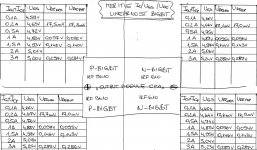
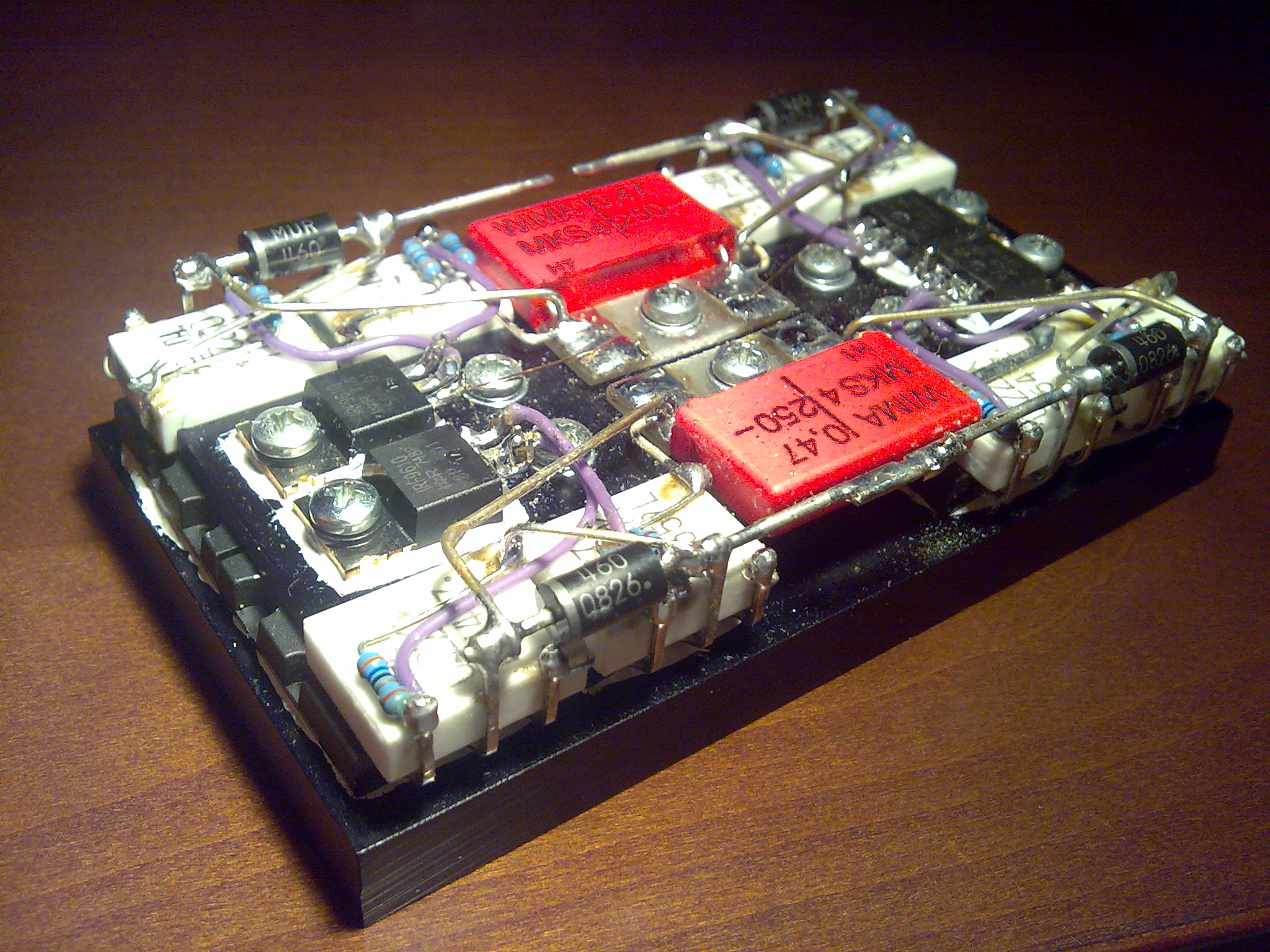
BIGBT linearity
OK, here's the comparison table of measurements of four independent BIGBT's mounted on the same Alu-module block. I was really shocked how close the results are considering that BIGBT's are actually compound components ... 🙂
Similarity of Ugs at 3A is incredible and there is noticeable convergent tendency at even higher amps. 😉
Attachments
Last edited:

I don't consider that good matching.
At 100mA Id I see 40mV of spread in Vgs.
This goes up to 80mV of spread as the Id is increased towards 3A.
Look at the transconductance average at 2A to 3A. ~130mV increases the Id from 2A to 3A.
Now apply 80mVgs differential to the FETs and guess how much the current will vary from your measurement point. You may well see upto 20% of Id variation if you could measure these FETs at the same Vgs and at the same Tj & Tc.
That's why I don't think = good matching, not with possibly 20% variation between highest and lowest samples.
Did you match the Source resistors? Judging by the Vre data shown it looks like ~1% between pairs has been built into your assembly.
This goes up to 80mV of spread as the Id is increased towards 3A.
I don't know what you mean but at 3A of output current I see Ugs variation from 5,20V to 5,25V, that is exactly 5,225V +/-25mV and that I consider as perfect. 😀
- Home
- Amplifiers
- Solid State
- The Very Best Amplifier I Have Ever Heard!!!!