alex, I think you can use Linear Systems LSK389A in metal TO-71 case, witch is pin compatible with 2n5565.
dado
dado
Alex
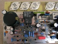
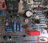
I looked at your PCB (photo). It is just a practical adwise: To achieve the desired and equal voltage on both side on the front end, I first mounted two resistors vertical. These two I connected with a third resistor, which was mounted horizontallyned (imagine the letter U turned upside down). In this way, I dropped to dismantle PCB from the heat sinks to get to the PCB from the underside every time I needed to change the value of R32/33.
To morrow I will start to work on a stabilized power for the front end. Our measuring on Goldmund so far has shown that it is neccesary to take steps to make the amplifier much more stable than it has shown so far. "Better power" to the front end will, I hope, solve some of this problems.
I have nothing to criticites how Goldmund perform. Very musical. It is detailed without beeing "overfocused". The top is the best I ever heard at home. Illusion of space is large, wide and with the ability to place the individual instruments and groups in the right place on the scene.
This is of course completely subjective observation, but is also based on comparisons with two other good amplifier, one with tubes and one with transistors. I hope to get to the back at a later time with a more in-depth listening impression.
I am really looking forwar to hear results and impression from other builders
Eivind Stillingen
I can’t fid any ware (here) these 150uF/63V(C5,C6), can I put the 220/50V witch I have in stock or go for the 220/63V or 100/63V, 47/63V
Last edited:
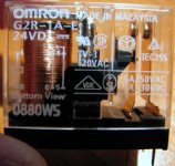
Alex what is the name part number and source of the relay on the board?
Again thanks for all your help🙂
Again thanks for all your help🙂
Newer mind. Stupid questionI can’t fid any ware (here) these 150uF/63V(C5,C6), can I put the 220/50V witch I have in stock or go for the 220/63V or 100/63V, 47/63V
Liliya thanks for adwise , I will do like you suggest .
Krisfr , relay could be buy from here Elementy i podzespo?y, cz??ci elektroniczne. W ofercie m.in. MOLEX, FLUKE, RICHCO, SUNON, OMRON, TYCO, SCHRACK, KINGBRIGHT, KONTAKT CHEMIE, HIRSCHMANN, ANALOG DEVICES, AMPHENOL, AMP, 3M in europa .
Alex.🙂
Krisfr , relay could be buy from here Elementy i podzespo?y, cz??ci elektroniczne. W ofercie m.in. MOLEX, FLUKE, RICHCO, SUNON, OMRON, TYCO, SCHRACK, KINGBRIGHT, KONTAKT CHEMIE, HIRSCHMANN, ANALOG DEVICES, AMPHENOL, AMP, 3M in europa .
Alex.🙂
Attachments
Last edited:
How high bias do you recommend for 2SK1530/J201. ( I know that that is subjecting view but approximately..)
How much current they like?
How much current they like?
Last edited:
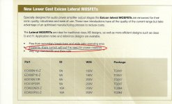
Yo should not use those MOSFETs in this schematic as they are not lateral type.
The bias setting should be done with themperature sensing element, as Vbe multiplier.
dado
The bias setting should be done with themperature sensing element, as Vbe multiplier.
dado
As far as i know they are not so temperature sensitive, they are practically ratelas, (but not)
the 1530/201 are vertical mosFETs.
Their temperature characteristics are completely different from Laterals.
In fact virtually all their characteristics are different from Laterals.
Their temperature characteristics are completely different from Laterals.
In fact virtually all their characteristics are different from Laterals.
I replaced the relay, because I found one with a higher current drive, I got the output transistors mounted on an L-shaped angle, and so on .......I understand that there is no need to ad source resistor ?
Alex.🙂
Alex.🙂
Attachments
Hi Alex,
That is what Nagys had always said 'no need of source resistors' but that is also many members are pointing their fingers at.
Just do it w/o source resistor first but do not let yourself destroy the option to use that resistor. If I were you, I would use a soldering slug (or a 5+3 washer) to make the mounting screw come into contact with the pcb (no soldering) and just in case.... It is always good to open yourself a back door first, right? You might have all that on your mind, but just in case if you might be overhwemed by 'closing to the finish line' excitment, here is some coolant for you. Just my 2 cents opinion.
Please try to post some results if you got any progress. Tks.
I forget this :
Anyone who had placed order prior to Jan15 but haven't yet got their boards, please show hands and check with your local post office, maybe? I have only 3 sets left with me and should I hold these for re-issue purpose until everyone had got their boards and send them away again, just in case...
Anyone who had placed order prior to Jan15 but haven't yet got their boards, please show hands and check with your local post office, maybe? I have only 3 sets left with me and should I hold these for re-issue purpose until everyone had got their boards and send them away again, just in case...
I replaced the relay, because I found one with a higher current drive, I got the output transistors mounted on an L-shaped angle, and so on .......I understand that there is no need to ad source resistor ?
Alex.🙂
Now you have gone and changed to a relay that is NOT available here in the states......😡
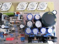
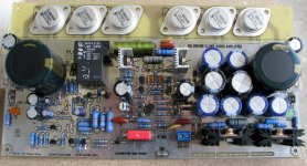
Your board are looking as good as they can get... I HOPE that they sound nearly as good as they look... 😀
Did you build more than ONE?
what is the part number for the PCB mount power connections spades...and lugs, to connect the power supply wires to the PCB?
These are the ones I am talking about... And the other side that the wires connect to.🙂
Digi-Key - 1285K-ND (Manufacturer - 1285)
go to catalog page to see more options
If you matched them then you can probably get by without the source resistors.I understand that there is no need to ad source resistor ?
Alex.🙂
What have you decided for your bias current?
Josip-del wrote:
Does someone know how much current passes through these transistors BD249C BD250C.
This have been answered before and jacco vermeulen has even given a very accurate calculation in # 1353.
Melon Head if you go back and start to read from # 1297 you will find some
proposal to your question on bias through output FET.
Eivind Stillingen
- Home
- Amplifiers
- Solid State
- The Very Best Amplifier I Have Ever Heard!!!!