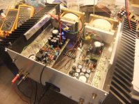
Almost the same results on both channels. DC "jumps" up and down. I think this will stabilize after I have choosed "earthing metode". First I will try "star-earthing" with connection to chassis at the input socket.
Problems so far: T7/8 very hot.
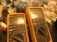
80 V DC = power front end. 0.4 mV = DC output.
To morrow: Listening test and may be some measurements.
E.S.
Problems so far: T7/8 very hot.
80 V DC = power front end. 0.4 mV = DC output.
To morrow: Listening test and may be some measurements.
E.S.
Attachments
Last edited:
This is really state-of-the-art!
Congratulations, much better than expected.
Good luck, and be careful, watching all revisions that have been done by Alex and bigpanda.
Regards,
Max.
Congratulations, much better than expected.
Good luck, and be careful, watching all revisions that have been done by Alex and bigpanda.
Regards,
Max.
I am anxious to build this as well...
2 questions though:
1. Is the power supply on board or do we have to provide our own?
2. What size of heatsink would be needed?
Thanks.
2 questions though:
1. Is the power supply on board or do we have to provide our own?
2. What size of heatsink would be needed?
Thanks.
Liliya,
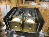
That is massive. Are you going to put some mechanical support on the other edge (opposite the bracket) of the pcb ? Whole setup weighs over 30kg, I guess?
That is massive. Are you going to put some mechanical support on the other edge (opposite the bracket) of the pcb ? Whole setup weighs over 30kg, I guess?
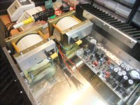
Lilia, very nice... but why didnt you mount the pcb onto the heatsinks directly?
You loose gain much thermal resistance using the L pieces.
You loose gain much thermal resistance using the L pieces.
Hi Liliya
Very good effort and results.
I hope your measurements be good.
I expect the result.
T7,T8 hot?
you used MPSA93-MPSA43 or other?
Very good effort and results.
I hope your measurements be good.
I expect the result.
T7,T8 hot?
you used MPSA93-MPSA43 or other?
I am anxious to build this as well...
2 questions though:
1. Is the power supply on board or do we have to provide our own?
2. What size of heatsink would be needed?
Thanks.
2x10,000uF electrolytics on board, and rectifiers off.
It seems heatsink must be at least as huge as Liliya's!
For smaller sizes, try some fan cooling.
Regards,
Max.
Almost the same results on both channels. DC "jumps" up and down. I think this will stabilize after I have choosed "earthing metode". First I will try "star-earthing" with connection to chassis at the input socket.
Problems so far: T7/8 very hot.
80 V DC = power front end. 0.4 mV = DC output.
To morrow: Listening test and may be some measurements.
E.S.
I remember a picture posted before where there is a heatsink mounted on T7/T8 position on the mimesis 9 board. See attachement.
Attachments

Nikosokey wrote:
T7,T8 hot?
you used MPSA93-MPSA43 or other?
I used MPSA 92. I will look at R16 (150 ohm)
T3,T4,T5 and T6 also MPSA 42. R11 changed to 10 k. To morrow I will try to find the right value for R23. 330 ohm is a bit to low for the source restistors (0,22 ohm).
Bigpanda wrote:
Are you going to put some mechanical support on the other edge (opposite the bracket) of the pcb ? Whole setup weighs over 30kg, I guess?
Yes, it is a heavy "box". I do not find mechanical support on PCB to be necesarry.
Telstar wrote:
Lilia, very nice... but why didnt you mount the pcb onto the heatsinks directly?
You loose gain much thermal resistance using the L pieces.
I can not see how that is possible using To-3. Explain.
I did the first listening test to day, not a serious one, but to check that is was a "hole trough" the Clone. Very often I listen to how equipment
cope with applause to jugde Hi-Fi quality. Clone was very good. No tendesy to "shattered glass ". More detailed listening tests to come later on bigger and better loadspeakers and better input signal.
Cooperation with the Roar continued Friday morning.
Eivind Stillingen
Someone send me a circuit that is 95% resembling this (it uses 2SK1058 instead) and it says an alternative to 2N5566 would be 2N3958. Could this be of any good?
Liliya,
I don't mean your chassis needs support in the middle. I mean the pcb is just 'hanging' on 1 edge and with so many caps on it, I think it may be nice to support the other edge of the pcb to relief the mechanical stress on the pcb.
PB
Liliya,
I don't mean your chassis needs support in the middle. I mean the pcb is just 'hanging' on 1 edge and with so many caps on it, I think it may be nice to support the other edge of the pcb to relief the mechanical stress on the pcb.
PB
(NOTE: For the protection circuit, MPSA93/MPSA43 can be replaced with MPSA92/MPSA42 without any further changes.)
T7 (MPSA93) = MPSA92
T8 (MPSA93) = MPSA92
T9 (MPSA43) = MPSA42
T10 (MPSA43) = MPSA42
T11 (BSS71) = MPSA42
T12 (BSS74) = MPSA92
C8 (100uF) = 150uF
C11 (100uF) = 150uF
C1 (47pF) = 100pF
C3 (4.7pF) = 8.2pF
C5 (4.7pF) = 8.2pF
C6 (4.7pF) = Omitted
R10 (1K) = 1K5
R22 (30K) and R19 (30K) = Replace with a single 10K ********
R20 (270) = 330 ******
Liliya do you make these two changes?
Telstar wrote:
Lilia, very nice... but why didnt you mount the pcb onto the heatsinks directly?
You loose gain much thermal resistance using the L pieces.
I can not see how that is possible using To-3. Explain.
why to-3 would make any difference? It's the L bar that adds thermal resistance.
If i'm wrong please somebody correct me.
If you mean how possible would the mounting be, it is possible using some little cables then soldered to the pcb 🙂
See also the picture of the original Mimesis.
To3 are either mounted on a bar attached to the back of the sink
or
secured to the front of the sink with the pins showing though on the inside for connecting to the PCB.
Is there another method?
or
secured to the front of the sink with the pins showing though on the inside for connecting to the PCB.
Is there another method?
Single Flanged Heatsinks
What do you all think of Single Flanged Heatsinks.
http://www.conradheatsinks.com/welcome.htm
Rudy
What do you all think of Single Flanged Heatsinks.
http://www.conradheatsinks.com/welcome.htm
Rudy
Attachments
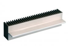
Component Mounting Flange
The flanged mounting feature, as seen on type MF30-1F-75 for example, is designed to improve thermal conductivity, provide greater ease of assembly and savings in cost compared to a fabricated heatsink and right angle bracket arrangement. By eliminating the thermal junction between heatsink base and bracket with a single piece heatsink, component temperatures are significantly reduced. (See diagrams below)
For example, the thermal resistance of the interface between a right angle bracket with cross-section 40x40x6mm bolted at 50mm. intervals to a flat backed heatsink (including thermal grease), has been measured at 3.5 C/W/cm2. The corresponding figure for Conrad flanged heatsink is virtually zero.
The Conrad flanged single piece heatsink (left) has more effective heat flow
than a conventional fabricated heatsink.(right)
Attachments

- Home
- Amplifiers
- Solid State
- The Very Best Amplifier I Have Ever Heard!!!!