Discouraging :
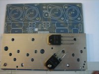
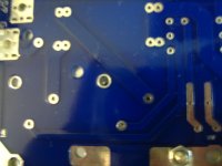
I don't think the TO-3P can be used on the TO-3 version board unless the board had to make modification again. I have include 2 photos so you can take a look. The screw thru the mounting hole for the TO-3P are not in contact to the flange (ie, the Source). So can't see how the Source of the Ps can be connected to the Source on the TO-3 on pcb.
If we mounted the TO-3P as shown in the photo (so as to fit the G & D and I think that is the only way to do so) the Source leg of the TO-3P will be too short to have anything to do on the soldering side. I am using a 4mm thick bracket.
Does anyone has any better idea?
Encouraging :
If we can insulate the 2 mounting screws on the TO-3 from the copper trace on both sides of the pcb, we may just use a solder lug to connect the upper hole to the output trace if we don't want the 0.22ohm. If do want the 0.22, we can solder one end of the resistor to the lower screw with a solder lug and the other end to trace near the other hole. That way we can still include the Source resistor. Hope I am describing it clearly.
Attachments
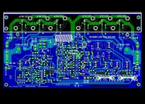
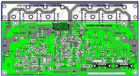
Bigpanda - This latest PCB from Alex is a work of art and a complete perfection. And it's very faithful to the original Goldmund Mimesis amplifier. Can we please go and order the boards now? I agree with Alex, it's time to take the next step, or we'll be here making minute changes forever.
I want to start building and also start a new thread on the process to help everyone who will be building alongside.
I want to start building and also start a new thread on the process to help everyone who will be building alongside.
Isn't it pretty hard to find those old metal cans? I think it's funny that it went from something not too terribly hard to get, to something very hard to get. Going to limit how many people can even build this amp.
Alex, can you please make the holes for the large snap-in capacitors 2mm? All snap-in capacitors come standard with 2mm legs in the 4700uF-10,000uF.
Dougie085 - You're wrong as usual. They're available from nearly all large electronic parts distributors. Take a look at Farnell and Newark (More than 4000 in stock!). Look at the Magnatec BUZ900/BUZ905 and BUZ901/BUZ906. Alfet just came out with a new line of TO3 MOSFETS similar to Maganatecs. Also the various Exicons are readily available from Profusion.
Last edited:
Thank you Alex! Can you generate and get the Gerber files and original Sprint files to Bigpanda? So he can get the group buy going.
I want to thank you for your hard work again. There will be a lot of happy diyers 🙂
I want to thank you for your hard work again. There will be a lot of happy diyers 🙂
Nice !
I am very interested in this project. Count me in for the kit. I am now designing a good switching PSU that could handle this type of load.
I'll get at it during the winter season. I am now thinking of 3 phase power for a 8 channel system.
I am very interested in this project. Count me in for the kit. I am now designing a good switching PSU that could handle this type of load.
I'll get at it during the winter season. I am now thinking of 3 phase power for a 8 channel system.
Well I don't appreciate the person attacks of the "as usual", but I was referring to the original devices used as I thought this was a clone?
For those who would like to etch their own boards, would Alex kindly provide, say, PDF files for both sides?
Thanks a lot.
Regards,
Max.
Thanks a lot.
Regards,
Max.
Magnatec BUZ900/BUZ905 MOSFETS are identical to Hitachi 2SK134/2SJ49. The only difference is that they're from a different brand. How does that not make it a clone?
With that type of logic we would have to use the original Philips capacitors, Vishay resistors, Huber & Suhner wire, Vampire binding posts, etc.
It's ok to use different brands for parts, as long as they're equivalent. And yes, it will still be a clone 🙂
With that type of logic we would have to use the original Philips capacitors, Vishay resistors, Huber & Suhner wire, Vampire binding posts, etc.
It's ok to use different brands for parts, as long as they're equivalent. And yes, it will still be a clone 🙂
PDF files ....not useless ?
....circuit is double sided with metallised holes, such as electrolytic capacitors how will soldered on top ground plain 😕?
....circuit is double sided with metallised holes, such as electrolytic capacitors how will soldered on top ground plain 😕?
Would LS5911 from Linear Systems fit 2N5565? Would you kindly point another equivalence for that part? Thanks.
Max.
Max.
When drilling the holes for the board in the NORMAL places(holes) right next to the necessary ones needed for parts like the Electrolytic, drill a small hole in the pad and solder a short jumper in it or two if the pad is big enough and needs it. Think and innovate.....circuit is double sided with metallicized holes, such as electrolytic capacitors how will soldered on top ground plain 😕?
Smartx21 - There is no current equivalent to 2N5565, but that shouldn't scare you away. There are hundreds of electronic parts distributors on the web that sell them. It's a readily available part. I posted some quick options, please go to this thread and read post # 34:
http://www.diyaudio.com/forums/group-buys/175296-pcb-order-goldmun-clone-4.html
http://www.diyaudio.com/forums/group-buys/175296-pcb-order-goldmun-clone-4.html
Well it's just you went on and on and on about the hitatchi devices being superior to everything earlier in the thread, so I wasn't sure.
Nagys
I want your comments:
Transformer: The seller told me that the transformer I bought was 2x70 VAC. My plan was to unwind down to 2x60 VAC. To day I have measured, and the transformer turns out to be 2x50 VAC.
---Quote (Originally by ivodonchev)---
2. Lowering the +/-80V at output stage down to +/-50V will NOT LOWER the power of the amplifier and will not increase THD. I think that Goldmund's reason to use 80V is probably sonic performance not measurable. At the some time with +/-80V at high power and 4 Ohm load the output mosfets will go out of power range easily. Probably that's why they use not oversized transformers and only 4700uF capacitors because this will give around 73V at high power and low load. This will be a little bit safer for output mosfets.
---End Quote---
According to what "ivodonchev" claims, 2x50VAC will be ok for the output stage. But what about the input stage? From an earlier post I remember that you said the power to the input stage should be taken from the 60VAC before the bridge. Will 50VAC be “good enough” for the input stage?
If not, can the last 10VAC be created in the way I did when I built my LFA 50 years ago:
A 2 x 9VAC transformer together with another 2x22VAC in order to achieve 2x 30VAC.
In the “Golmund case” 9VAC together with my 50VAC (1000VA, overkill I know) = 60 VAC for the input stage.
(For those who are interested search for LFA50 and look at the power schema).
Have you read my proposal about source resitors in post 1038 for those who want that possibility?
Nagys says:
"I want to start building and also start a new thread on the process to help everyone who will be building alongside".
I am looking forward to this help from you. A very good offer.
Eivind Stillingen
- Home
- Amplifiers
- Solid State
- The Very Best Amplifier I Have Ever Heard!!!!