We need help! If anyone is familiar with Sprint Layout, can you please be kind enough to go here http://www.diyaudio.com/forums/group-buys/175296-pcb-order-goldmun-clone-5.html and help Bigpanda finish laying the circuit, so we can all proceed with the group buy 🙂 It would be extremely appreciated.
Alex, if you can help, can you please contact Bigpanda? Thank you everyone for your time!
Alex, if you can help, can you please contact Bigpanda? Thank you everyone for your time!
If you want freaky - how about Naim's use of an 800VA transformer to drive a preamp.
Many voltage regulators running many class A pre circuits and class A op-amps can draw an excess of current if the designer so desires. I'd have to assume that was the case...or was it made from 80 nixie vacuum tubes and all the required heaters sucked amps hard?
Dude, I got a tone arm here in my shop that draws 7amps from 120vac! I don't say it is bad but...it is WACKY. Who said audio had to be green? BTW I'm talking tone arm NOT the platter motor.😉
But this "talk" is all out of line. I'll rest my finger tips and hope this thread gains fruitful momentum.
JAH BLESS
Last edited:
I posted some extremely useful information for potential builders, please go here to read it: http://www.diyaudio.com/forums/group-buys/175296-pcb-order-goldmun-clone-6.html
If you looking for 2SK1058/2SJ162, you can purchase matched pair to quartet for reasonable cost atYes for repairs
Tech DIY Company Store
I bought from him to repair my Hafler 9505 amp which used 4 pair lateral and rated 250w at 8ohm and 375w at 4ohm. Fairly conservative rating than the Goldmun clone.
Efficiency
I think you all needs to be educated about power amplifier efficiency:
Amplifier Efficiency
Hope this helps
I think you all needs to be educated about power amplifier efficiency:
Amplifier Efficiency
Hope this helps
Now if somebody would proto these Goldmund board(s) and run it through some paces...then you may end up with another "Krell KSA50 Clone" type thread...but who ever did finish THOSE K50 builds anyway?
He he...wink wink ...
Carry on as ye were...
me
Hi , tinitus I'm agree but I have placed 4W resistor far as possible from electrolytic caps , to not be heated and dry , this is the main reason . From start my layout was PCB sigle side with somes jumpers to be more easy for guys to build . I'm working now an PCB with protection ,and power supply on main board .Sorry for my bad english .
Alex .
Alex .
Many voltage regulators running many class A pre circuits and class A op-amps can draw an excess of current if the designer so desires. I'd have to assume that was the case...or was it made from 80 nixie vacuum tubes and all the required heaters sucked amps hard?
Dude, I got a tone arm here in my shop that draws 7amps from 120vac! I don't say it is bad but...it is WACKY. Who said audio had to be green? BTW I'm talking tone arm NOT the platter motor.😉
But this "talk" is all out of line. I'll rest my finger tips and hope this thread gains fruitful momentum.
JAH BLESS
ha ha😀
My tests found the amp lacking into low impedance loads granted I have a preference for electostats and ribbons so it is nowhere near a Pass Labs or Krell in that regard. I have to say Goldmund is very vague in stating their specs. I would like to know for instance power into eight ohms and the power into four ohms or two ohms (if possible) to gauge the current dilivery of the amp.
Jam
Acording to the data sheet here are the power ratings
8Ohms 250W rms
2Ohms 250W rms
1Ohm 150W rms
16Ohms 150W rms
3Ohms 400W rms
Alex - I'm interested in your new board design with the protection circuit on the same PCB. Bigpanda, lets wait for Alex to post this PCB layout before we proceed further. This will make building the amp a lot easier.
PCB main amplifier + PROT + PSU
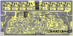
Hi, as I say few post ago , PCB with PROT and PSU so , here I am 🙂 glad to share another bad design full of errors .Somes comments are welcome to make necessary corrections until final PCB . I'm sure you do not like the location of the final transistors , and not only this . I'm ready to draw again , in other way if you don't like how it looks my PCB .
Alex.
Attachments
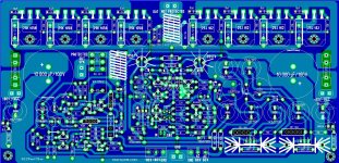
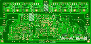
Eye candy is right..............
Keep up the good work Alex, you have talent.
Jam
P.S. If I were to build this board I would keep ac away from it, let rectificion and voltage doubling occur somewhere else. My
Keep up the good work Alex, you have talent.
Jam
P.S. If I were to build this board I would keep ac away from it, let rectificion and voltage doubling occur somewhere else. My
Last edited:
thanh,
Like I said the does not come close to doubling its power into four ohms unlike most high end amps. They threw a three ohm spec into the mix to confuse the issue much like the time when Pioneer rated their recievers into six ohms rather than the customary eight.
Most customers will go for the high number when they dont understand the conditions the device is being tested under. If I am not mistaken eight ohms and four ohms are the industry standard.
Regards,
Jam
Last edited:
I'm sure you do not like the location of the final transistors
what's there not to like 🙄
with spacers between board and transistors to releave the stress it should work nicely
and the board could easily be turned around with transister at lower half of heatsink
looks perfect, exstreme 😉
any ideas about the lowest possible voltage that will work 😕
Tinitus - Regarding lower voltage, please take a look at my last several posts here: http://www.diyaudio.com/forums/group-buys/175296-pcb-order-goldmun-clone-6.html
Alex, the board is looking good! I see you have provided two different places for the speaker output, one protected and one not protected, I like that. I'm assuming that most builders will use the protected output. In addition to the series inductor, can you also please locate the output Zobel next to it? They really should be together in the same place. If possible, can you please update the following few things?
1.) Is there any way that you can make the tracks for the 60VAC larger? Especially the points where the power supply connects to?
2.) Can you make it so that the original parts, BD249C/BD250C will also fit?
3.) The fuses should be between the 100uF and 10,000uF capacitors.
4.) Any way to run the -80VDC to the protection circuit, the other way? Maybe first going down and around the circuit board. I don't know if it's good to run it straight across the input stage circuit and right over the negative feedback trace.
5.) And lastly, can you please make the +/-80VDC connection points next to each other (so they're not on the opposite sides of the board) and closer to the bottom, where the 60VAC connection is? This way, power supply wires wont have to be run to different sides of the board and right over the circuit.
Thanks!
- Home
- Amplifiers
- Solid State
- The Very Best Amplifier I Have Ever Heard!!!!