This is a VERY HIGH BANDWIDTH amplifier.
Although no one has addressed the Ground Plane issue that I raised a long time ago. Goldmund choose to have a board with a Ground Plane. I think they knew what they were doing. Those ferrite beads are not window dressing, smack of bleeding edge parasitic oscillations.
I personally choose NOT to build this amp it without it as is.
TEST and Test and test again, before a group buy is initiated.
Caveat Emptor
I will not raise this issue any more, but I strongly urge someone, anyone else to do so.
I hope I am wrong, but having built an very High Bandwidth amp in the past, I strongly suggest it, the ground plane, is a necessity.
You imagine this or that, based on your experience...your skills..you belief, your calculations... and you suppose things.....yep... alike all of us...but......
Reality is another stuff.
I would not say anything without listen first...well.... people is different.... i have enormous respect by the reality...and very low respect about theories and suppositions....but people goes travelling in this long horizontal cursor..from the rigth to left....i am half way in the reality side...... ahahahahahah!... i think so....who knows.
I have build so special things...so nice and theorically perfect, made by wise and skilled guys and gave a shot on the board so awfull result the sound reproduction.... that i would not be surprised if this one is really "the best wide world amplifier" or the "worst lemmon on earth"
regards,
Carlos
That is why I do as you do now .. first get it working , then comes the human feedback , change this compensation , that compensation. Different tail and VAS currents , all will change the final sound. Different devices , BJT or FET .. different sound. Some amps will tolerate a wide range of operating conditions , some will not. It is problematic financially to build a whole amp just to see how a particular variant of a design sounds. Better to go modular , worst case build another 5$ input/voltage stage. When you "lock down" a design both objectively and subjectively (time and use) , then make a dedicated board that has no options as you already have the best.
This amp could very well be the best as shown , we would need to know WHICH mpsa42/92 , a detailed photo of the main board , ALL the finer details of the sourcing and layout. If not built exactly like Goldmund did , we could be frying out laterals and/or input stages on a weekly basis. A real "Lemmon' 😀
OS
Oh yes, I did use a different CCS... Forgot about that. Although at normal listening levels input voltage is below 100mV, since this amp has so much gain. Considering this it may not be that important, at high power levels crossover distortion may swamp whatever is contributed by the CCS. Will test this.
I wonder if the CCS was designed with temperature drift in mind. IIRC, 6V zeners have the lowest tempco, and the two transistors cancel their tempcos. But what does maintaining operating point achieve? Or perhaps a specific tempco was decided for the CCS, to compensate for the tempco of the FETs?
- keantoken
Groud plane ?!?
Hi, about GM
I'll explain somwthing which can break someone from a lost way.
There's no groud plane for reduce any error, it has only power plane and output plane on the top & bottom of PCB.
Ferrite beed used for fix all pins to heat sink and easy to screw !
If you look at PCB you'll found a groud section only power junction, there's no relation to signal path because signal path are in the module which contains temperature compound and included specific haetsink !
Heart of Gm are matched parts and selected smd resistors for control THD & IMD.
I have them onhand and try to modify they many many way and I found manything wrong when I change brand & type of their parts.
Thanks
Anadigit
This is a VERY HIGH BANDWIDTH amplifier.
Although no one has addressed the Ground Plane issue that I raised a long time ago. Goldmund choose to have a board with a Ground Plane. I think they knew what they were doing. Those ferrite beads are not window dressing, smack of bleeding edge parasitic oscillations.
I personally choose NOT to build this amp it without it as is.
TEST and Test and test again, before a group buy is initiated.
Caveat Emptor
I will not raise this issue any more, but I strongly urge someone, anyone else to do so.
I hope I am wrong, but having built an very High Bandwidth amp in the past, I strongly suggest it, the ground plane, is a necessity.
Hi, about GM
I'll explain somwthing which can break someone from a lost way.
There's no groud plane for reduce any error, it has only power plane and output plane on the top & bottom of PCB.
Ferrite beed used for fix all pins to heat sink and easy to screw !
If you look at PCB you'll found a groud section only power junction, there's no relation to signal path because signal path are in the module which contains temperature compound and included specific haetsink !
Heart of Gm are matched parts and selected smd resistors for control THD & IMD.
I have them onhand and try to modify they many many way and I found manything wrong when I change brand & type of their parts.
Thanks
Anadigit
Last edited:
Hi,
I had my running shoes ready except :
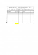
1. the slight variation in board size and if 205 x 88 is the final, I would say the ceiling price is us$14 / pair. See post 94, 187, 188 for previous approach.
2. I still have to see Alex's gerber files (top_silk, bottom, soldering mask, drill) for the boards.
BTW, the price is for the main board only. Any more info I should include on my status report? Never organized any GB before. (or unsuccessful)
I had my running shoes ready except :
1. the slight variation in board size and if 205 x 88 is the final, I would say the ceiling price is us$14 / pair. See post 94, 187, 188 for previous approach.
2. I still have to see Alex's gerber files (top_silk, bottom, soldering mask, drill) for the boards.
BTW, the price is for the main board only. Any more info I should include on my status report? Never organized any GB before. (or unsuccessful)
Attachments
This circuit is also not unstable, barring any disastrous layout choices.
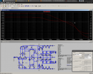
Open loop gain is a conservative 53db, with impressively well-defined HF behavior, thanks to the heavy degeneration. Phase margin is 75 degrees, which is not bad at all.
- keantoken
Open loop gain is a conservative 53db, with impressively well-defined HF behavior, thanks to the heavy degeneration. Phase margin is 75 degrees, which is not bad at all.
- keantoken
Attachments
i've seen plenty of references to the ferrite bead on the originals. I assume its to solve problems with parasitic oscillations at high frequencies. Should they be considered for this design?
That is a totally different amp. It doesn't even use MOSFETS. It is much faster too, as far as I can tell.
- keantoken
- keantoken
parb - Goldmund used ferrite beads on all of their amps with plastic MOSFETS. They never used ferrite beads with the metal can MOSFETS. So yes, you should probably use them with the 2SK1058s/2SJ162s. The beads go on the gate and drain legs, NOT on the source leg.
Oh yes, and the original CCS contributes hardly any distortion at normal listening levels, and at higher levels crossover distortion swamps it. So I opted for it instead of the "better" CCS, to stay truer to the original.
Here is the simulation package, as close as I could get it to the original. If you want the .model statements to go away you can right-click on them and select "invisible" from the drop down menu. They will reappear the next time you open the schematic.
V1 and V2 were used instead of a 60VAC source to simplify operating point solution and eliminate drift from SPICE results.
- keantoken
Attachments
Thanks Krisfr.
Ok, lets address the "Ground Plane" issue... A "Ground Plane" is where the circuit board is covered in metal on the components side of the PCB. Only leaving small amount of space where the actual holes are where the components mount and also where the mounting holes are located.
Alex, would this be difficult for you to create? We would need a printed view from the component side of the board.
Rudi_Ratlos and bigpanda, will having a ground plane significantly increase the cost of the PCB boards?
I agree with Krisfr and think it would be worthwhile to implement this. After all, the Goldmund amplifier where this schematic was taken from does use a "Ground Plane."
We are going from a single side to a double side. There will be a definite rise in the cost, by how much? I would have to get quote from vendor first .
I've been told that ground planes aren't just something you "do". It takes skill to use one and improperly done may give a worse result.
Ground planes minimize stray inductance at the expense of more parasitic capacitance, which minimizes resonances. It also shields traces from each other, reducing interference.
- keantoken
Ground planes minimize stray inductance at the expense of more parasitic capacitance, which minimizes resonances. It also shields traces from each other, reducing interference.
- keantoken
Thanks keantoken. Any and all other thoughts regarding the "Ground Planes" are welcomed, so we can decide which boards to do a buy on.
My advice would be to open a new thread presenting an initial ground plane PCB for discussion, so all the gurus will notice it. I think this would be the most efficient way to go about it. It would also allow us to go on discussing mundane things here.
- keantoken
- keantoken
True, but since a lot of the people who will be purchasing these boards are here, it would be nice to get their opinions before the group buy.
Alex, thank you so much for posting the .pdf files!
Alex, thank you so much for posting the .pdf files!
Nagys,
...............ground plane? I thought that you told us you were an engineer, maybe you should explain to us what kind of engineer you are. You have a circuit on the verge of instablility and any deviations in layout could lead to oscillation.
Which means that there is a real possibility of some members, who don't have the required test equipment, blowing out their speakers if everything is just not right with the board layout.
You also need to identify compensation points that can be used to quell any oscillation if they exist. What about stability into reactive loads?
I don't mean to put a damper on this and I hope there are no problems with the final layout but you have to be very cautious with a design like this.
Jam
- Home
- Amplifiers
- Solid State
- The Very Best Amplifier I Have Ever Heard!!!!