No, it is 2nd order lowpass. It appears as a bandpass because well below tuning the output must track the input. That input is from a driver. That driver has a falling response. The input to the port, the falling response from the driver, is the output from the driver with the 2nd order group delay added. 2nd order lowpass.Uh 4th order coupled resonator (bandpass), 360 degrees behind.
Were it actually a true bandpass that asymptotes to zero at DC, there would be decreasing port output as the signal approaches DC. That would require that there be no output to manually pressing the cone in slowly and leaving it pressed in. That's an easy demonstration that it is not a bandpass.
The reason for the phase being 270 degrees out-of-phase is that from our perspective in the front, the input to the port is initially 180 degrees out-of-phase being the rear output of the driver. Add in 90 degrees at Fp from the lowpass and the result is 270.
The system response is 4th order. It asymptotes to zero at DC, with a 2nd order driver rolloff and 2nd order port rolloff that both asymptote to zero at DC.
Dave
Last edited:
This post #632 is the only- http://www.diyaudio.com/forums/multi-way/166411-measurements-when-what-how-why-64.html#post2215596
This only works well if the second amp is trimmed to have unity gain under load. .999-1.001 is close enough. .95 is not.
Maybe there is a thread, or should be? There are a lot of ways to put a driver in the feedback loop.
I don't see the speaker in a feedback loop here - the diagram shows 2 amps bridged, no more, no less.
Lukas
wintermute- that is a perfect example of what a phase flip/mode change normally looks like. I do not know why this aberration does not show on the Z curve, it should. Everything else looks pretty normal except the other curves seem suspiciously smooth to me. Maybe it is a good driver and really that smooth but I suspect some other factor may be in play. I really do not believe the phase plot on the frequency response graph. At mechanical resonance a normal driver has no phase shift as all reactance should be in balance which means phase should be zero.
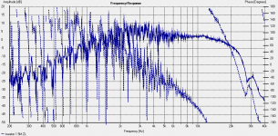
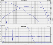
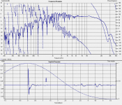
Hi Sum, here are the warts and all measurements and some in between 😉
The one I posted at lunch time was an export out of holm, imported into speakerworkshop so was limmited what I could show with it.
Below are the following: (all the same measurement)
raw response (basically unusable but put in for reference).
gated at 3ms (which is probably what was in the speakerworkshop graph
1/32nd octave complex smoothing.
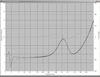
I've also attached the raw unsmoothed impedance curve and the same zoomed in on the 5k - 7k range.
I believe that the phase must be pretty close (well relatively between the drivers anyway) as when I modeled the crossover using the measured responses of the individual drivers, the modeled response was VERY close to the measured response of the implemented crossover. Perhaps the Display of the phase is not correct? My first measurements DID have problems with the phase, and the modeled crossover was not in agreement with the actual results at all. Interestingly the maufactureres specification for this tweeter is that the resonant freq is 700 Hz certainly not what the impedance plot shows!!
The impedance plot I am very confident is correct 🙂
Tony.
Attachments
Last edited:
Many (more than half) agree here that matched pairs are needed for a stereo effect. How about taking the two speakers that are supposed to match and carefully placing them side by side and driving the two speakers with the exact same signal with the polarity of one speaker opposite of the other speaker. Place the microphone carefully, at some distance, exactly on the center line between the two speakers under test. Next take the measurement of response and so on and discover the "residual" signal. The two speakers should pretty much cancel out if the path length to the mic is the same for all the drivers. Run the same test with the speakers in phase to form a second curve of their composite response. The difference between the two curves might be a good measure of matching, depth of null, and so on.
Anyone interested to try this to post or of have comment will write?
🙂=SUM
The direct field will cancel well if the level matching is good. The reverberent field will remain so you will only see a maximum amount of rejection based on how low the reverberent field is. Now if you get the speakers closer together then the reverberent field will cancel to a higher frequency. If your drivers are in a line then you can place speakers face to face nearly touching and get very high cancelation to a high frequency.
Basically, when units are a wavelength apart they add the same in power terms, whether in phase or not.
David
40Hz is 25ms behind, 25Hz is 40ms behind which is defined as echo, yuk!
Hello SUM
Have you looked the the Group Delay curves in a box program?? Unless I am missing something I don't see that at all. Sure there is a delay but it's not fixed and not as extreme as simply 1/F
Rob🙂
The mass of the VC + former does become a dominating factor for the low pass cut off point, however, isn't inductance as well. I've changed on axis response just by changing dust cap shape, so this tells me inductance is also a very important factor. I was just interested in the actual VC configuration during the test you mentioned. Other aspects involve so many paramters that it's impossible to come to any conclusion. Mechanical impedance is an important aspect, however, since it's a value independent of shape, one cannot draw predictable results from that value.soongsc- the voice coil layer count does not really matter. It is the mass of the voice coil compared to the mass of the cone-surround system where the velocity of propagation through the cone is significantly different than the velocity through the voice coil. For practical purposes the velocity through the voice coil is near that of copper metal but somewhat less. For paper process cones the velocity is much lower through the cone than through the VC. For ceramic cones the velocity is much higher in the cone than in the voice coil. Both cases lead to a mechanical impedance mismatch. Matching the masses is the electrical equivalent of termination of a transmission line- much less reflection from the connection.
Small ports- yes compared to the driver size. Less than 1/3 the area of the active driver is pretty much a joke! We say it lets the bass escape so there is not any. Mostly all small ports do is allow midrange out the port. This is because the port will go into power compression long before the driver does. Exact measurement showed a .7 cubic foot box with 6.5 inch driver and 2 inch port power compression occurred at 85dB at the port tuned frequency of 40Hz. Passive radiators do not do this and block the midrange from the back escaping through the port. Ports/passives have a lot of other troubles like the output from the port/passive is one full cycle behind the active driver at the port tuned frequency in an ideally tuned system. 40Hz is 25ms behind, 25Hz is 40ms behind which is defined as echo, yuk!
...
Port design is also an interesting aspect because we normally assume round port. In reality, combination of duct length, duct shape, port shape, port termination, and port cross section area are all critical to the nature of the port; lets also not forget the box volume is also critical, which is one aspect that inspired development of the T/S parameters.
wintermute- Beautiful graphs! That loading on the tweeter could surely affect the phase. To bad there is not a common dome tweeter in your hand. Speed bump in the phase curve is clearly visible. Also note the mechanical resonant frequency and electrical resonant frequency are clearly different.
speakerdave- I do all my testing out in an open foot high grassy field which alleviates a lot of testing problems. Not much first reflection and no reverberation for a long way. No building nearby or anything. With this in mind there will be lobes formed up high but if the speakers are matched there will still be a null on axis though difficult to measure at high frequencies (like above 4kHz) as you say. Thanks for the feedback.🙂
soongsc- 2 layer. The dust cap certainly changes things a lot if it is glued directly to the voice coil and not the cone. Seas uses the 35mm dome as a dust cap on a different driver which has a 35mm VC. Whizzer cones always attach to the VC and not up the cone somewhere as the voice coil moves and the cone sits (or goes modal/breakup) when the decoupling occurs. Use a lot of Walmart undercoat on metal dust caps and all JBL woofers. JBL really knows how to make a driver which always sounds like it is shouting no matter the output level in SPL.
Port delay- the way I said it was really muddy like the sound of a port. At port resonance in an ideally tuned system using a Q=.383 driver and optimum box and port....... The port and cone always move in the same direction at the same time above port tuned frequency. The port is not in quadrature with the driver. The drive signal for the port starts out as the back wave of the active driver at -180 degrees. This signal is coupled through the spring of the box to the mass of the port. This causes 180 degrees of delay, which is frequency dependent, so both always move together between Fs and Fport. Motion must be this way or the port and driver would fight each other and response would not be flat. In non-ideal systems the two do fight which causes ripple in the response. The delay time for the port increase with decreasing frequency until the port resonant frequency is reached. The delay through the port is always 180 degrees between Fport and Fs and can easily be calculated as 1/2 the cycle time of the port tuned frequency at the tuning frequency. Further, the stored energy causes the port to continue to have output after the active driver stops. To me this really smears the bass badly if the port tuning is in the range of 20Hz-40Hz. Above or below that frequency range I do not experience the smear near as much or the lack of impact of a coupled resonator system. However, sealed low Q boxes sound and test best to me.
Large ports, compared to driver size, work fine but still have the problem of escaping midrange out the port. This is one reason I prefer passives. Another problem is the port is far more sensitive to room loading and ever other room LFE under the Sun. I quit resonant tuned/resonant peaked systems long ago.
If someone can explain how the port has output before the active driver moves I would be very interested. The description above is exactly how the mechanical system works. My models are all mechanical not using Thiel or Small for anything. See Susan Lee and Micheal Lampton (Lamton?) if interested.
This is a discussion about ports and not really about measurement. A whole lot more can be found in the subwoofer threads.
robh3606- Believe I have already said to much about what I think about most of this software and phase/time measurements. The systems agree within themselves but has anyone given it a reality check? At resonance there should be zero phase. If that is not there how am I to believe the rest of the phase is correct?
robh3606- Believe I have already said to much about what I think about most of this software and phase/time measurements. The systems agree within themselves but has anyone given it a reality check? At resonance there should be zero phase. If that is not there how am I to believe the rest of the phase is correct?
Hello SUM
So you are saying all the box programs are wrong?? You are the only one to get it right?? Using 1/F is the way to find the Group Delay in reflex box?? It doesn't change with Frequency so it's always constant??
Let's see the Group Delay in a reflex box vs. Frequency the way you calculate it?? Pick a common driver, a box volume and a tuning frequency and we can compare so we can all see where the differences are??
Rob🙂
Please do not make statements so black and white. Many different programs do some things correctly and do other things incorrectly. Really do not know about your software in particular. I do not use box programs as testing several of these has lead me to find different errors in each. I pretty well explained how time/phase is calculated so you can do that as you like. Group delay is just the group of frequencies near the filter point. As you said a low pass and as I said a bandpass. We already do not agree on the model so... take that as you like. Have pointed out several times at resonance there should be zero phase in a tweeter or in the mechanical model it is -90 degrees at resonance because the linear motion region is below the Fs and at resonance a second order low pass is at 90 degrees. However if it is treated as an acoustic transducer and call that zero then, we am sure many understand as I am sure you will. Being one of the first to design computer models in 1975 became well aware of how a model could trick a user by showing things not as expected or relative to a different set of conditions or premise. No need to argue here I think. Put an accelerometer on a cone and on a passive and measure motion directly. That will be the real answer.
The DMS-37 tweeter measured is indeed a common dome tweeter, only with a small bit of horn loading that increases its sensitivity on-axis. In all other respects, it is typical, so there is no reason to dismiss his measurements as atypical.wintermute- Beautiful graphs! That loading on the tweeter could surely affect the phase. To bad there is not a common dome tweeter in your hand. Speed bump in the phase curve is clearly visible. Also note the mechanical resonant frequency and electrical resonant frequency are clearly different.
I've measured dozens of tweeters myself, mostly soft dome, over many years. Not one has ever shown any non-MP response and certainly none have any sort of "phase reversal". I have quite a number of pages at my site with full documentation of tests and experiments and also downloadable files, both SPL and impedance. The phase reversal does not occur. If it did, it would be accompanied by a corresponding SPL anomaly. That does not occur.
You asked about the Parts Express DC28F. I have a full page evaluating it with some improvements that one can make, as for many other drivers, several also presented. That and a set of pages of downloadable measurements can be found at the links below. None show any hint of any phase reversals anywhere.
Dayton DC28F-8 analysis
Raw Measurements Pages with Test Conditions Specified
The FFT of the measured impulse response as specified in those pages results in a point spacing at 5KHz of about 2Hz or better. The measurement systems (plural) are not making errors at this level. This is also rather far below the typical breakup area, so it is not a breakup situation unless it can be shown that a soft dome tweeter is indeed breaking up in this region, unlikely. The only other source would be an internal reflection, but that is readily measured and is accompanied by an SPL anomaly. Even in those cases, the deviation is M-P and is readily shown to be so. That's not speculation, that's documented and easily reproduced.
It also cannot be an artifact related to the dome geometry as this is an issue related to wavelength and in any case cannot change dramatically.
There is nothing in the response of a typical dome tweeter that can remotely explain the claimed phenomenon.
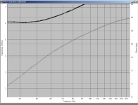
Simply not true. The port is without question a lowpass device. The attached graph (if I uploaded it properly) shows the response of a port with a BW2 lowpass at 40Hz for a flat wideband input. It's evident that at 20KHz the response is nearly 180 out-of-phase. Even at 1K it's almost the same. Clearly at Fp the phase has shifted 90 degrees, exactly what one would expect from a BW2. There is one and only one place where the port moves in the same direction as the driver, that is at the asymptote at DC. Above that, there is an increasing delay. That's the classic group delay. This is indisputable.The port and cone always move in the same direction at the same time above port tuned frequency.
What does complicate things is that the input to the port as we measure it from the driver front is 180 degrees out-of-phase. All output from the port that we measure and perceive (excluding box vibrations) are from the start originating from a signal that is at its start 180 degrees out-of-phase. The port then adds its lowpass response, a slope with a group delay, to its input. That delay is decreasing as frequency drops to the asymptote at DC where the driver and port are precisely 180 degrees out-of-phase from our external perspective. For practical purposes they are never fully in phase as the port output is so attenuated by that time that its moot, in the noise floor.
Quadrature has nothing to do with it, since most real ports have other issues associated with box internal dimensions and port self-resonances.
As far as the box delay, that is primarily a function only of the time delta from driver to the port controlled by the speed of sound in air in the box. The resonance of the system is primarily a function of the air-spring of the port air mass and the box air spring with some coupling of the air in the port and the air in the box, so that complicates it in details, but as a lumped sum response for purpose of discussion, this can be ignored.
This is correct up to the last point that is wrong. Study the phase response of the BW2 acoustic lowpass and you'll see why. Even in an "ideal" ported system, at tuning the drivers do not move in unison. The output from the port can only be 90 degrees out-of-phase with whatever the input signal is.The port is not in quadrature with the driver. The drive signal for the port starts out as the back wave of the active driver at -180 degrees. This signal is coupled through the spring of the box to the mass of the port. This causes 180 degrees of delay, which is frequency dependent, so both always move together between Fs and Fport.
I fully agree with your assessment as to the "sound" of a reflex system, I much prefer the PR for the same reasons that you describe. But that is a separate issue from any analysis of the reflex system.
Agreed, the analysis does not require Thiel/Small to be analyzed at this level. It's fundamental physics of acoustics.If someone can explain how the port has output before the active driver moves I would be very interested. The description above is exactly how the mechanical system works. My models are all mechanical not using Thiel or Small for anything. See Susan Lee and Micheal Lampton (Lamton?) if interested.
Dave
Attachments
So if 0.4Hz signal is applied to the active driver of a passive radiator system (say tuned to 40 Hz) the passive and the active will move together? Is that correct in what you are saying? That is near DC and therefore should be representative as it is two decades below the tuned frequency.
Not going to argue this port thing any more. I accept my measurement models and yours do not agree. The Dayton tweeter I have measured and it flips phase at 4500Hz. Why your test system does not get it I do not know. Mine clearly has shown it in two different test systems.
I am going to say to each their own method and there is no way to prove this to me or to you (collectively) without a showdown and listening experience. Once an in phase system is heard, as I define, there is no doubt there is something grossly wrong with all other system which are not. I have done this many times with many studio engineers and the non-in phase system always gets an ugly face from the engineer and comment of how poor what they thought was good sounded.
Please accept this from me and I will accept your position from you so we can move on to other aspects and results which are more useful to everyone including me.
One more thing- I have not seen one system except the two/multi tone test which will reliable measure phase response. Every automatic and software based system has shown errors in making time/phase measurement that I have tested against two/multi tone derived data from known systems. This is why when designing a new speaker that is the method used here.
Best regards to all
=SUM
Last edited:
I've measured dozens of tweeters myself, mostly soft dome, over many years. Not one has ever shown any non-MP response and certainly none have any sort of "phase reversal". I have quite a number of pages at my site with full documentation of tests and experiments and also downloadable files, both SPL and impedance. The phase reversal does not occur. If it did, it would be accompanied by a corresponding SPL anomaly. That does not occur.
Dave
Thank you!
I've been scratching my head over these comments too.
David Smith
Yes, the passive will move nearly simultaneously with the woofer, though it moves out when the driver moves in, of course, and vice-versa. The results as measured outside of the box is that the output from the PR is nearly totally out-of-phase with the driver as measured outside of the box. Both asymptote to 0Hz at DC so they will not be fully 180 degrees out-of-phase at anything but DC. How much difference depends on the system, of course. To describe it as moving "in sync" could be confusing, since a PR could just as easily be on the front as the back, so direction in/out is more appropriate. Press in on the driver and the PR moves out. I've never encountered a PR system that did otherwise.So if 0.4Hz signal is applied to the active driver of a passive radiator system (say tuned to 40 Hz) the passive and the active will move together? Is that correct in what you are saying? That is near DC and therefore should be representative as it is two decades below the tuned frequency.
I wouldn't call this a measurement model, its just a model to match the physics. There are measurements and there are models. And I would offer that what I presented is not "my" model.Not going to argue this port thing any more. I accept my measurement models and yours do not agree.
For someone unfamiliar with the many test systems in use today, at least evidently mine, you have previously had much to say that seemed to be conclusive on your part as to the problems they have. It's a method in exceedingly wide usage with proven track records. All systems are limited, yes, but it's doubtful that so many "do not get it". In comparison to detailed anechoic chambers measured with swept sines, they perform rather well. Certainly a swept sine would show the phenomenon as it would be manifested in the SPL response. I cannot recall any such results shown by anyone DIY or manufacturer.The Dayton tweeter I have measured and it flips phase at 4500Hz. Why your test system does not get it I do not know. Mine clearly has shown it in two different test systems.
The point about listening tests is not applicable to this part of the discussion. I'm not taking any stance on system designs and perception and that's not what we've been debating. You might be surprised, I suspect that agree more than we disagree on that aspect from your posts.
I have no problem agreeing to disagree, but if a post has what appears to be errors, it is not the place of anyone to say that one should "accept a position" and move on. This is DIY with a lot of readers that could be misinformed. I learn from these threads as well, so I'm certainly not going to take something as gospel because someone simply says it is so. That is why I presented my points with as much factual background as reasonable for now and as accurately as I could. If you find fault, please say how and back it up.Please accept this from me and I will accept your position from you so we can move on to other aspects and results which are more useful to everyone including me.
I have nothing against your methods for design. However, your entire point of reference is your measurement method that you imply invalidates the results of practically every other system extant with no hard data. Don't expect many to accept that without taking exception, especially without any hard data in support.One more thing- I have not seen one system except the two/multi tone test which will reliable measure phase response. Every automatic and software based system has shown errors in making time/phase measurement that I have tested against two/multi tone derived data from known systems. This is why when designing a new speaker that is the method used here.
Dave
Last edited:
Sumaudioguy,
I'm still curious to know who you are.
Some posts (from everyone, not just you) are their own self contained proofs. But most throw out many statements, expressed as fact, but not generally regarded as such.
The reality is, I will consider that type of unsupported statement based on the person making it. If dlr, john k, Dr. Geddes makes a comment, even if there is not a proof following, I may give that a different weighting.
Sure, it's your right to be somewhat anonymous and coy. Being anonymous has its credibility issues however.
mark k
Please do not make statements so black and white. Many different programs do some things correctly and do other things incorrectly. Really do not know about your software in particular. I do not use box programs as testing several of these has lead me to find different errors in each. .....
Im not very clear on your point about black and white. Your posts are always black and white, right and wrong type stuff so I do not follow why you would ask others to not be the same way?
Im also not clear about your POV on box programs. Are you saying something like the popular WinISD program is incorrect and should not be used? I have built many sub designs, IB, ported, PRs, sealed, etc. I have also built 6 sets of speakers all of the builds used WinISD to calculate my box and/or ports. The end result matches the sim. The port velocity, driver excursion issues are pretty predictable. I have also read probably 200+ builds online that also use a box program like WinISD. They have had a succesful conclusions.
So with a mountain of data supporting WinISD I wonder what you think is so inaccurate with something like WinISD? Further, Why isn't there a "Fix WinISD" thread somewhere if there is flaws?
Sumaudioguy,
I'm still curious to know who you are.
Then put your Sherlock hat on. I found out in less than two hours with no more info available than you have.
Sure, it's your right to be somewhat anonymous and coy.
Full anonymity is something everyone should have the right to.
Being anonymous has its credibility issues however.
I can assure you he has been around the block and is making statements from a "been there" POV.
Not going to argue this port thing any more. I accept my measurement models and yours do not agree. The Dayton tweeter I have measured and it flips phase at 4500Hz. Why your test system does not get it I do not know. Mine clearly has shown it in two different test systems.
=SUM
The problem here is that there isnt another measurement out there that confirms your opinion. Not one other person agrees with your position either yet so how can you expect anyone to just take everything you post at face value?
Like others I have tweeters sitting around to measure. Im measuring them and I have no idea what you are talking about with the phase flipping.
You are next going to say that HOLM is an inaccurate measuring tool? Dr Geddes supports it and believes it to be accurate and he is well helluva hard core science guy.
HOLM inaccurate....OKay, Used ARTA. Is that inaccurate too?
I actually think there is something too keeping the phase under control and its one of the reasons Im working on getting the DEQX with brick wall filters and phase alignment so Im not disagreeing just for fun.
I can assure you he has been around the block and is making statements from a "been there" POV.
Hello Cal
That's all well and good but there is a literal mountain of data that says otherwise. It just doesn't agree with the positions being posted. I have 3 different box programs and all agree about the Group Delay numbers for a specific driver/box tuning. None of them come up with 1/F as the maximum delay number even at the tuning frequency. More importantly the delay changes with frequency so it's not a hard number.
Keeping your identity a secret is everyones right but it doesn't help when there is no supporting data and no explanation as to what the issues are with software that is used by thousands of people to design their speakers everyday. Things have changed since 1975.
I have had no issues using my software. The only time it has been wrong is due to my mistakes such as a lousy measurement or a wrong measurement loaded into the sym.😱 It's kinda hard form this side to believe your software is flawed when your own experience doesn't support that view. It gets really hard when it's from "The Mystery Man"
Cosmic Debris FZ 😀
Rob🙂
He may have been around the block, but he's still making some rather curious errors of analysis and statements that are in at least one case easily disproved all while seeming to be indignant about responses that challenge the unsupported claims.I can assure you he has been around the block and is making statements from a "been there" POV.
Dave
- Status
- Not open for further replies.
- Home
- Loudspeakers
- Multi-Way
- Measurements: When, What, How, Why