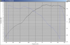
ok, so here is what I dialed in by ear that sounds flat in the bass. This is from 5 spots across the couch where I listen. I was sitting in my usual soft seat for the graphs just in case my fat head absorbs bass.

Funny that during the sweep it doesn't sound flat though during music all is fine. The dip at 50Hz is readily audible during the sweep while at 180 or 190, it sounds flat. Now hear, I mean here comes the crazy part. This graph is all the way up to 20kHz, same bass data showing:
Any thought on this? I mean I know Fletcher-Munson and all, but that seems extreme and doesn't graph all that differently that before.
Dan
Funny that during the sweep it doesn't sound flat though during music all is fine. The dip at 50Hz is readily audible during the sweep while at 180 or 190, it sounds flat. Now hear, I mean here comes the crazy part. This graph is all the way up to 20kHz, same bass data showing:
An externally hosted image should be here but it was not working when we last tested it.
Any thought on this? I mean I know Fletcher-Munson and all, but that seems extreme and doesn't graph all that differently that before.
Dan
A couple quick turns of the knobs got me this:

By comparison, the old graph just sounded muddy. The ear stinks at judging audio in my experience.
No matter what speakers I've had in this room, I've always had that 600Hz lump. Any ideas on that?
One other question, the sub level is about half of what it was yet the 30Hz bump barely moved. WTH? Shouldn't that be linear?
Dan
Last edited:
Hello David,
i would expect every mode change to be visible
in the impedance plot - if spreaded wide enough - and
in the frequency response as well.
Since a mode change goes hand in hand with a change in
driving point impedance - bending wave transducer slang -
there has to be a change in phase too.
The strongest modes such as edge resonances in woofers will give the odd minor wiggle in an impedance curve. If you want to see more you can subtract the stationary impedance from the motional impedance, otherwise you seldom see evidence of the various vibrational modes (although laser analysis may reveal a large number of minor modes).
As to "phase flips" without corresponding significant amplitude response aberations, I've never seen it. That would be dramatic non-minimum phase behavior.
Got an example?
David
Seriously, I always try to boost the bass when doing it by ear. It's not exactly long term, but this sounds much better now. Maybe it's just my mind knowing the graph looks better and it's a trick, but it just sounds so much less muddy now.
I should also add that the reason the dip at 50Hz is so audible is b/c things stop vibrating for a second during the sweep.
Dan
I should also add that the reason the dip at 50Hz is so audible is b/c things stop vibrating for a second during the sweep.
Dan
Last edited:
The strongest modes such as edge resonances in woofers will give the odd minor wiggle in an impedance curve. If you want to see more you can subtract the stationary impedance from the motional impedance
snip
When the sound output isn't solidly tied to the motor, driver design becomes a secret art (or a muddle-through pragmatic craft) instead of engineering.
When the sound output is tied to the motor, you can use the motional impedance (using a Wheatstone Bridge to zero out the stationary impedance) for feedback upstream to the amp. Today, that's a great open loop in reproducing sound.
Seriously, I always try to boost the bass when doing it by ear. It's not exactly long term, but this sounds much better now. Maybe it's just my mind knowing the graph looks better and it's a trick, but it just sounds so much less muddy now.
I should also add that the reason the dip at 50Hz is so audible is b/c things stop vibrating for a second during the sweep.
Dan
Not even worth two-cents, but by my eyeballing the pictures, you've cut the prominence of that yuccky lower bass region (often prominent in tuned boxes and shorty horns) but kept the wonderful bump-up at 16-foot pitch, 32 Hz, and you just can have too much of that. Your system must be great for French organ music.
I've been "listening" to bass-content recordings recently on my spectrum analyzer. A lot of what passes for low bass is stuff at 50-65 or even 80 Hz and pretty rare to see lower content. Good to control that region but, as I said, you can never over-pump output below say, 40, where a whack at the side drum can feel really satisfying if your system plays it loud enough.
I've been fooling more with my loudness button (kind of has a built-in loudness-variable Fletcher-Munson function). Beginning to feel you can't escape the necessary logic that equal-loudness curves really do matter unless you always play at the same level. And if and only if that listening level is loud enough (and we are talking really loud), there is no discrepancy between measurement and ear. In a word, that is why most everybody cranks up the bass after doing basic frequency tests.
Example: "the drum is as loud as the singer"... when played loud but "hey, where did that drum go"... when played softly.
Last edited:
Are there any links on the "feedback loop" topic?
This post #632 is the only- http://www.diyaudio.com/forums/multi-way/166411-measurements-when-what-how-why-64.html#post2215596
This only works well if the second amp is trimmed to have unity gain under load. .999-1.001 is close enough. .95 is not.
Maybe there is a thread, or should be? There are a lot of ways to put a driver in the feedback loop.
You got me thinking Ben(this could be trouble). When I was a younger man I hated the very kind of loudness button you refer to. When the volume went down, the bass seemed to get too high. My thought was that the recording engineer probably has no loud button in the booth, they're mixing it to where is sounds good to them, and they're probably listening at a typical, not extreme level. I was a teenager then so much has changed.
I think I see now that this is where you (wrongly I might add😉) accused me earlier of not knowing psych 101. Certainly I'm not the best educated person, but... a rather brash statement. No hard feelings. Funny that I never like a treble boost. At normal listening levels though, my hearing is still good up to 15k or so if my monitor headphones are flat to 20k. I think that's what I hate about a lot of the big box store systems--too much treble in general.
So I'm still not convinced that the volume dependent loudness button is a good thing as this still sounds great at low levels, but I do have a huge boost down deep. Of course I hear pretty much no bass right now with the volume low. When I play my bass softly, the low end doesn't seem to stay spectrally equal to my ear and this is what I was getting at before. It still doesn't seem like a good idea to me from an intellectual perspective to have a variable loudness button. I'd think that since your brain anticipates less bass when the level is low, the spectral content of the output should be the same regardless of level. In the end though, it's what you prefer. If you want it to sound like it does at normal volumes, that type of loudness button needs to be used. Also, being a musician changes what you want to some degree. A bit of that in Dr. Toole's book.
Now I got to get out some organ recordings. Great fun if you can find good ones. Thanks for the idea.
Thoughts?
Dan
Last edited:
This post #632 is the only- http://www.diyaudio.com/forums/multi-way/166411-measurements-when-what-how-why-64.html#post2215596
This only works well if the second amp is trimmed to have unity gain under load. .999-1.001 is close enough. .95 is not.
Maybe there is a thread, or should be? There are a lot of ways to put a driver in the feedback loop.
... as long as the voice coil relates in a predictable way to the the sound output, using your approach which (using a Wheatstone Bridge to annul inductance too) I think is the only cogent approach.
Sum,About 1977. The graph was generated when later test strongly suggested 1.25 inch was right for a nominal 6.5 inch and the 15 inch referenced during the time at Altec of Anaheim. The blue line was based on another driver that worked pretty well. Years later 1.25 inch is still the preferred size even though mine 6.5" have 1.5 inch voice coil. Credence could not supply 1.25 inch voice coil so the cone had to be made heavier and the efficiency was compromised as well as flatness of frequency response and of course that made cone breakup worse.
Please realize this is for normal cone drivers used for as much bandwidth as those might offer. Special needs change requirements like cost or whatever. I also believe the line probably should not be dead straight but then how to bend it?
Oh yes, thanks Cal.
🙂=SUM
From the date, I assume the voice coil is a single layer coil? What kind of coil wire size was used in the test?
By small, I guess you mean compared to driver effective area by a certain ratio.🙂 I do recall some measurements posted in either Speaker Builder or Audio Amateur. But I'd also think port mouth design also plays an important roll.Small ports are evil and therefore should always be blocked.
...
dantheman- Would you have a simple soft dome tweeter with no lens you could test?
Hi Sum, attached is a 1.5M on axis measurement of a morel DMS-37, I don't have the original measurement on my laptop so this is what I imported as an FRD into speakerworkshop.
There is a glitch around 5.5Khz but my feeling is that it is baffle related rather than inherent in the tweeter. The phase shows a bit of a glitch here as well, but nothing like the flip you are talking about, so I don't think this one is going to help.
The impedance plot has been 1/64th Octave smoothed, otherwise it looks rather "hairy" Interestingly it shows no sign of any glitch in the range I would have expected it.
I don't have any unbaffled measurements of this tweeter.
Also not sure what you mean by "no lens" The DMS is semi horn loaded, so may not be what you are looking for anyway.
Tony.
PS. on the anonymity issue, I think it is quite a good tactic, allows someone to get un-biased feedback based on the ideas themselves , rather than on who it was that had the ideas 🙂
I took offense to comments earlier in this thread that I was a nobody and should not dare to question something an expert has said. It is true I have no Audio qualifications, I'm just a guy who has read some books, asked questions, experimented and had a go at designing my own speaker from scratch. Does that mean I'm unworthy of contributing to discussions, in which experts may be involved? Note I would like to make clear, it was not the experts themselves, that I am aware of, who took anything I said as threatening.
If an expert posts under the veil of anonymity then critical discussion can be had without the issue of bias creeping in. In my opinion, any theory, or opinion put forward, should be judged on the merits of what is being said, rather than on the credentials of the person putting it forward.
rant off 😉
Attachments
Tony, I don't know who said what, but I'll apologize for them. I mean it's DIYAudio, not industry professionals only. We all appreciate their contributions, but there's nothing wrong with civility.
Anyway SUM, can we get a bit more about the driver in the feedback and it controlling break up? A before and after would be noice. I wish I had known so many companies were doing this. Makes me want active monitors even more. I'm going to do some Googling. I just don't see how it can do it b/c it seems it would be a cone problem.
Thanks,
Dan
oh, as far as VC size, Tony's break up sure looked nice and his VC is half the diameter as his cone. You know I'm big on break up.
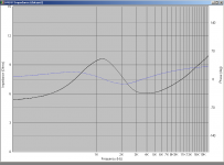
The strongest modes such as edge resonances in woofers will give the odd minor wiggle in an impedance curve. If you want to see more you can subtract the stationary impedance from the motional impedance ...
Yes, that is basically what i have done in the plot below ...
It is a bending wave transducer not a conventional woofer.
... otherwise you seldom see evidence of the various vibrational modes (although laser analysis may reveal a large number of minor modes).
As to "phase flips" without corresponding significant amplitude response aberations, I've never seen it. That would be dramatic non-minimum phase behavior.
Got an example?
David
I am not quite sure if i understand that right. But e.g. even and odd
order modes tend to radiate with different efficiency. With low damping,
mode changes will show up even in the frequency response.
Maybe there was a misunderstanding. With sufficient damping magnitude
and phase is both smoothed. I did not deny them being interconnected.
Kind Regards
Attachments

Last edited:
Cone breakup modes change from driver to driver in the same production run. Am not including situations like "drum head mode" in this statement as that can be somewhat controlled for consistent results. Examples are curved cone 15" woofers as found in today's PA and the "biflex" radiator of yesteryear~1975. Random breakup is for all practical purposes impossible to predict the pattern. Affecting the random breakup pattern can be done with cone edge treatment, surround material and treatment, and so on to every parameter of the moving and mounting system including the amplifier.
I have demonstrated on many occasions control of breakup by using a better amplifier much to many peoples surprise. Putting the voice coil in the feedback loop of a unity gain inverting amplifier really tames all breakup. See simple example of drawing. Power opamps.
This is for sure an interesting approach. But IMO it only helps to control
the velocity at the driving point. If there is an even order mode, which
may cause the driver to radiate rather inefficiently, reducing the driving
point velocity may even worsen the dip in FR.
I would expect the effect to be similar to introduction of damping at the
driving point. Also i would expect that modes with circular node
lines can be much better adressed this way than modes with radial
node lines. Nevertheless, together with the right amount of damping
in the surround this techique might be very helpful.
It does not solve the conflict, that a traditional driver designed for
rigidity and pistonic motion, will have poor modal overlap in the
frequency range where modal behaviour occurs.
When using a driver in its modal region, quality of transmission can
be ensured by high modal overlap. That - in the end - means
giving up the pistonic driver paradigm completely and design for
high modal density/overlap. Going that way you need not care about
feedback and the like, because you want the transducer
to behave modal and design for it.
On the other hand, going towards balanced modal behaviour with
low modal density is the paradigm of the "Balanced Mode Radiator"
patented by NXT. But balancing the modes then implies to modify
the distribution of mass and compliance along the radius of the driver.
Kind Regards
Last edited:
soongsc- the voice coil layer count does not really matter. It is the mass of the voice coil compared to the mass of the cone-surround system where the velocity of propagation through the cone is significantly different than the velocity through the voice coil. For practical purposes the velocity through the voice coil is near that of copper metal but somewhat less. For paper process cones the velocity is much lower through the cone than through the VC. For ceramic cones the velocity is much higher in the cone than in the voice coil. Both cases lead to a mechanical impedance mismatch. Matching the masses is the electrical equivalent of termination of a transmission line- much less reflection from the connection.
Small ports- yes compared to the driver size. Less than 1/3 the area of the active driver is pretty much a joke! We say it lets the bass escape so there is not any. Mostly all small ports do is allow midrange out the port. This is because the port will go into power compression long before the driver does. Exact measurement showed a .7 cubic foot box with 6.5 inch driver and 2 inch port power compression occurred at 85dB at the port tuned frequency of 40Hz. Passive radiators do not do this and block the midrange from the back escaping through the port. Ports/passives have a lot of other troubles like the output from the port/passive is one full cycle behind the active driver at the port tuned frequency in an ideally tuned system. 40Hz is 25ms behind, 25Hz is 40ms behind which is defined as echo, yuk!
wintermute- that is a perfect example of what a phase flip/mode change normally looks like. I do not know why this aberration does not show on the Z curve, it should. Everything else looks pretty normal except the other curves seem suspiciously smooth to me. Maybe it is a good driver and really that smooth but I suspect some other factor may be in play. I really do not believe the phase plot on the frequency response graph. At mechanical resonance a normal driver has no phase shift as all reactance should be in balance which means phase should be zero.
dantheman- yes sir one of these days will get around to measuring and demonstrating the effect of the driver in the feedback loop. Right now there is pressing work. Apologize for the wait. Also this thread- why do I do this instead of measure? Hummmmmmm?
LineArray- You are right and then somewhat incorrect. With the driver in the feedback loop as show in that post there is active control and not simple damping. Back EMF generated by the motion of the voice coil is met with an equal and opposite driving force, based on the gain of the unity amplifier, causing the motion to be canceled. This is not damping. This is why exact unity gain is required for control to work. Modal motion still occurs so you are correct concerning that. The main effect is to somewhat "lock" the voice coil to the drive signal using the feedback. This is why it affects all aspects of driver behavior, lower THD, controlled breakup, and so on. Voice coil motion becomes a mechanical version of the drive signal and not a free swing mechanism driven through a spring (resistance).
Last edited:
Match pair null test?
Many (more than half) agree here that matched pairs are needed for a stereo effect. How about taking the two speakers that are supposed to match and carefully placing them side by side and driving the two speakers with the exact same signal with the polarity of one speaker opposite of the other speaker. Place the microphone carefully, at some distance, exactly on the center line between the two speakers under test. Next take the measurement of response and so on and discover the "residual" signal. The two speakers should pretty much cancel out if the path length to the mic is the same for all the drivers. Run the same test with the speakers in phase to form a second curve of their composite response. The difference between the two curves might be a good measure of matching, depth of null, and so on.
Anyone interested to try this to post or of have comment will write?
🙂=SUM
This is not correct. A port is a 2nd order acoustic lowpass and as such is 3db down at Fp, a Butterworth in effect. This means that it is 90 (or 270 depending on point-of-view) degrees out-of-phase at Fp for a system tuning that yields a box rolloff with Q=0.707.Ports/passives have a lot of other troubles like the output from the port/passive is one full cycle behind the active driver at the port tuned frequency in an ideally tuned system. 40Hz is 25ms behind, 25Hz is 40ms behind which is defined as echo, yuk!
Dave
This is not correct. A port is a 2nd order acoustic lowpass and as such is 3db down at Fp, a Butterworth in effect. This means that it is 90 (or 270 depending on point-of-view) degrees out-of-phase at Fp for a system tuning that yields a box rolloff with Q=0.707.
Dave
Uh 4th order coupled resonator (bandpass), 360 degrees behind.
- Status
- Not open for further replies.
- Home
- Loudspeakers
- Multi-Way
- Measurements: When, What, How, Why