Please accept my apology in advance. I am trying make heads or tails of this long thread, and I am apologizing to those that know more than I do for the intrusion. BUT I have a few questions, and I hope to clarify for myself and maybe others some of the basics of this power supply.
First, is this a DIY project or a commercial one.
Is there a current schematic available?
Can I purchase up to date pcb for the project?
IF I can where and at what cost?
What output currents and voltage is this SMPS capable of?
Can I purchase parts?
What would the whole “KIT” cost if there was one?
Thanks for your thoughts if you share them….
Is commercial and DIY as well. We sell boards from latest version while we share all info from previous version.
We don´t share latest schematic version due chinese cloning.
As soon we move to a new version we make schematic public.
All SMPS ver2 boards have been sold.
Now we are moving to a SMPS ver.3 who will have following specs:
- 1500W
- regulated
- resonant mode
- PFC
- output voltage between +/-6V up to +/-150V
- full protection
You can download SMPS version 2 schematic from here:
http://vicol-audio.ro/img/smps/Sch_%20SS&Tubes_SMPS_rev2.1.pdf
More info here vicol audio : smps
Regards,
Tibi
Yes please, and the voltage across R19. It's because that the current is set too low for TL431 to work correctly and with the values specified on the schematic I had much less than 51V on 51 Zener diode. Please do it because I'm asking for this for the third time 🙁.Do you want to measure voltage across zener diodes ? 🙄
I also think that the voltage divider for TL431 is designed incorrectly - I mentioned it before. There is a simple formula to calculate the output voltage of TL431 (you can check it in the datasheet). It's:
Vout = 2.5(1 + Rupper/Rlower), where Rupper and Rlower are resistors in the voltage divider.
With the values on the schematic you get 52,2V wheras maximum voltage allowed for TL431 is 36V. I think that your circuit works only because the current through TL431 is too low - minimum current is 1 mA, otherwise it does not work. If you specify the voltage across R19, we will finally check this out.
As a result of too small current the voltage adjustment does not work in your SMPS (as you explained several times). But if you use correct resistor values suddenly it starts working. I can adjust the output voltage within 5V range.
I suggest that you search in google the following phrase to learn more about TL431: "designing with TL431". You will then find out how to calculate the voltage divider, whether the compensation helps and very interesting article from Christophe Basso http://powerelectronics.com/mag/50107.pdf on TL431 biasing. I think he is an expert on SMPS design.
Yes it works but I'm not happy with the noise on the output. It is even slightly more than 200 mV. This is exactly what Eva (our forum expert) mentioned several pages back. I wish she'd particiapate in this thread more. The level of noise is unacceptable and I'm trying to find out what is the reason. This may be the common-mode interference (as Eva mentioned), or a problem with the output choke.Glad you got SMPS working !
I have posted some measurements in this thread http://www.diyaudio.com/forums/power-supplies/149702-50v-smps-quasar-amps-others-9.html#post2038240 .

Yes, and you don't? Please read articles from Christophe Basso or from Ray Ridley.Do you think that compensating TL431 will improve SMPS feedback ?
Mark
Thanks Mark for this investigation. I´ll recheck and come back with my findings.
To reduce output noise use ferrite beads on each output diode and also on wirring from SMPS to your load.
Regards,
Tibi
To reduce output noise use ferrite beads on each output diode and also on wirring from SMPS to your load.
Regards,
Tibi
Application note from Hitachi: http://documentation.renesas.com/eng/products/linear/rej03d0678_ha17431.pdf gives example of calculations that apply to TL431 (page 17).
Mark
Mark
@djlove
I've realised that the picture with high load shows current masurement (10A) and not voltage. What was the voltage then? It looks like you did not assemble the feedback loop (the pot is missing). What parts did you use in the loop?
@Tibi
Have you any progress with the feedback loop? Did you measue the voltages?
Did you measure the output resistance of the SMPS?
I'm still not happy with the feedback loop in my SMPS.
Mark
@djlove
I've realised that the picture with high load shows current masurement (10A) and not voltage. What was the voltage then? It looks like you did not assemble the feedback loop (the pot is missing). What parts did you use in the loop?
@Tibi
Have you any progress with the feedback loop? Did you measue the voltages?
Did you measure the output resistance of the SMPS?
I'm still not happy with the feedback loop in my SMPS.
Mark
Hi Mark,
You can show measure on output dc (noise) with oscilloscope?
also pwm on primary trafo (with 50%load at output)? (or pwm at secondary power in ac) if you not have ISO probe.
I see this for understand problem of noise at output.
Regards
I can do only part of it. It's due to fact that I'm leaving tomorrow for 1 week (I'll be in Montenegro - I hope it's not that hot there 🙂).Hi Mark,
You can show measure on output dc (noise) with oscilloscope?
also pwm on primary trafo (with 50%load at output)? (or pwm at secondary power in ac) if you not have ISO probe.
I see this for understand problem of noise at output.
Please take into account that my oscilloscope is not of the highest quality (and I don't have a current loop).
The photo of the noise on the output was taken with 100 mV/div. The noise level greatly depends on the feedback loop settings.
I think that I know the reason for the noise: a typical common-mode choke cannot be used as an output filter. Such a filter should use a different magnetic material and the windings should be connected differently. At least that's what I think. I need some time to verify it.
At the moment the most important issue is the feedback loop.
I did some tests but I had only 4x100W resistors mounted on a heatsink and during the tests one of them started melting 😱 - I need a beeter load.


Mark
Hi Markus,
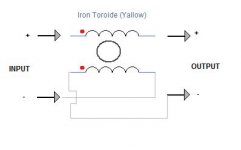
yes, in fact completely wrong, the toroid (material) and also the winding.
you have a toroidal iron powder (yellow)?
In this type of output circuit, the toroid to be used as impedance block and not as output filter. (in the picture the toroid used and the type of winding is typical of the EMI filter.(Ferrite and common-mode winding)
Last edited:
Hi,
Simple 2-wire coil in parallel but the polarity of input must be reversed (see pic)
on 30mm diameter, it is possible to wrap 14 turns (2x1, 24) or 16 (2x1,12)
after this it is convenient to Add the linear filter output (this psu does not have)
Regards
Simple 2-wire coil in parallel but the polarity of input must be reversed (see pic)
on 30mm diameter, it is possible to wrap 14 turns (2x1, 24) or 16 (2x1,12)
after this it is convenient to Add the linear filter output (this psu does not have)
Regards
Attachments
Thanks AP2. I'm glad you have confirmed my findings; a different material and a different winding connection. I'll test it when I come back from Montenegro.Hi Markus,
yes, in fact completely wrong, the toroid (material) and also the winding.
you have a toroidal iron powder (yellow)?
In this type of output circuit, the toroid to be used as impedance block and not as output filter. (in the picture the toroid used and the type of winding is typical of the EMI filter.(Ferrite and common-mode winding)
Is there a chance that it will decrease the noise on the output?
BTW, I checked that this noise is not audible in a speaker (I used 200W amp) but I still want to get rid of it. Can you give more details on the linear filter on the output you mentioned?
Mark
(Please stop me if I'm saying stupid things)
Why use that TL431-as-a-ccs-trick in series with the opto and the bunch of zenners which control the actual output voltage?
Why not use TL431 as what it is - a shunt regulator - with ref taken from a vout voltage divider and a-k series with opto led and resistor (as the other smps's use it)? And control the output voltage from the voltage divider (multi-turn pot if you want fine adjusting).
TL431 datasheet
Check the datasheet for the tl431 before connecting it in this form, you might exceed the specifications during normal operation. I think this supply would work by monitoring the postive rail only since this is not a dual tracking supply.The output inductor is wrong for this application,as mention in other posts.Depending on the output a value 35 to 100uH in each output should work and can be obtained using a ferrite (ETD29 or so) with a 1mm spacer in the outer legs 1mm wire size 14 to 16 turns for each and use an LCR meter to obtain inductance needed.From Brown's "Power Supply CookBook" a formula for inductance on page 46 L(min) = [Vin(max) - Vout]* Toff /1.4*Iout(min)
Vin(max) = highest pk voltage following output rectifiers for that output voltage
Vout = output voltage
Toff ~ about 30% of 1/fsw (switching frequency)
Iout is lightest load current expected.
example from book:
Vout = 28vdc
Iout = 10A
fsw = 100kHz
L(min) = [47V -28V](4.25us)/1.4(1A)minI =57.6uH
The 47 volts is 2*vout+diode drops in this case.
A formula for the transformer for HB:
Npri = VmaxE8/4*fsw*Bmax*Ae and for ETD 49
and 110/220 VAC operation: (382)E8/(4*50kHz*2800G*(Ae=2.11) = 32 turns refer to Brown page 123.
When power is switched on Voltage to transformer primary can reach over 380Volts and might saturate the core.
and Nsec = 1.1(50+1.2)*32T/(254-2)(.95)=8T
where 50V is desired ouput voltage and 254V is Vbulk(lowline),.95 is max duty cycle in this case.
If you have LTspice you can simulate your supply or any part of it,yes simulation can help...
Last edited:
Hello
from where did you get 2800 gaus and 385 volts?
This is halfbridge so the voltage should be 385/2 volts.
What core material did you use in that calculation?
Best regards,
savu silviu
from where did you get 2800 gaus and 385 volts?
This is halfbridge so the voltage should be 385/2 volts.
What core material did you use in that calculation?
Best regards,
savu silviu
Values
Hello and nice to hear from you
As was pointed out this is example that was taken from Marty Brown's "Power Supply Cookbook" pages 122 & 123 which is a complete design of a 280 watt halfbridge converter using cuurent mode control, the magnetics he used in this design are mentioned on page 123 along with his explaination of the parameters used in the calculations.
When not using a pfc and since this is offline 110/220vac converter at startup the voltage across the primary will be the bulk voltage and in the case of 220vac this would be about 380V,as the input filter caps charge and the control ic ramps up then the voltage will start to drop to the expected 1/2 of the bulk supply.In a spice simulation you can plot this.LTspice is a good one and is free and the one I use.All this will happen within a few ms.
I use ferroxcube core sets and different materials depending on design requirements and I derate Bmax dependent on the core loss and fsw but in the example I used 2800G which is well below the rating of the materials used by the ferroxcube product at that frequency which as the example points out should result in a steady state value of 1300 to 1500G for HB converter.
This was an example only to demo one method of calculation and there are many other methods published to accomplish the same results.
In Pressman's "Switching Power Supply Design" most of this is in a chart form for most topologies and the calculations are straight forward.
Last edited:
Well you must be right but take in account that if you want to draw 1kw from a smps you can use for HB 24 turns in primary at 50Khz without many headaches on ETD44. the problem is those few milliseconds.
in my case if i took those in account at start up i will be forced to use ETD49 as a core because of the space required for the primary and secondary windings.
those milliseconds don't count that much if you have voltage control or at least an over voltage protection circuit.
Best regards,
savu silviu
ETD44 core set
Maybe but I think you are on the border line with this core set,If your windings exceed the calculations based on wire size,window width,2mm safety margin and winding technique ie winding by hand this core set is small for 1kW and ETD49 core set would allow for this and you might be able to get 1kW @50kHz but think about this by changing a few components that would raise your fsw to ~100kHz you should have no trouble with the winding and you can obtain 1kW with the ETD44 core set with ease and reduce copper and other loses as well.I calculate @50kHz with ETD44 you can get maybe a solid 700watts,at 72kHz ~1kW and at 100kHz 1.2 to 1.3kW provided wire will fit.
Maybe but I think you are on the border line with this core set,If your windings exceed the calculations based on wire size,window width,2mm safety margin and winding technique ie winding by hand this core set is small for 1kW and ETD49 core set would allow for this and you might be able to get 1kW @50kHz but think about this by changing a few components that would raise your fsw to ~100kHz you should have no trouble with the winding and you can obtain 1kW with the ETD44 core set with ease and reduce copper and other loses as well.I calculate @50kHz with ETD44 you can get maybe a solid 700watts,at 72kHz ~1kW and at 100kHz 1.2 to 1.3kW provided wire will fit.
Last edited:
wire used would be litz and winding would be done by hand.
you are right .. constant 1kw with ETD44 is possible at around 75Khz with litzwire.
best regards,
savu silviu
you are right .. constant 1kw with ETD44 is possible at around 75Khz with litzwire.
best regards,
savu silviu
It sounds to me you have everything under control,fsw is almost always the key to a point then magnetics become a black art sometimes..
The magnetics are the key to every good smps.
In my opinion for a resonant smps at 125Khz the transformer is the most important piece of the smps.
Winding technique is essential for low leakage and low capacitance. the geometry of the core and the material itself is very important. That book that you quoted is the bible of smps design.
Regards,
Savu Silviu
- Home
- Amplifiers
- Power Supplies
- ±50V SMPS for Quasar Amps (& others)