ok, so the project does seem to be still moving along, but i'm glad I didnt plan around it. I do appreciate the effort to get it right though and i'm sure I will enjoy the regs when they do become a reality. I will use them on a different project to what I had planned though
I hear you. Believe me, it's frustrating to me as well not giving people a timely solution. I personally feel waaaay behind the schedule, if there was one. Sorry if it messes up anyone's plans. Rev 5k should be fine (famous last words) but I don't want to commit to any hard dates. I'm not running a company so I let the project run its natural course, not set by financial goals. In the same time I'd feel awful recommending you guys something that I know has some problem, however small.
At the moment free time in my life is something of an endangered species 🙂 Anyone who had children will know what a newborn does to your schedule/time. 😀
This being said, I am actively working on the project a few hours a week. Not everything I do is reported here. Sometimes I run all kind of tests that just confirm my own theories about the circuit, or otherwise.
So, everyone, please feel free to delete yourself from the GB list if you've lost interest. At some point I will order PCBs and probably it will probably be a larger number than what the list indicates, so that I don't turn away those who arrive late.
I hear you. Believe me, it's frustrating to me as well not giving people a timely solution. I personally feel waaaay behind the schedule, if there was one. Sorry if it messes up anyone's plans. Rev 5k should be fine (famous last words) but I don't want to commit to any hard dates. I'm not running a company so I let the project run its natural course, not set by financial goals. In the same time I'd feel awful recommending you guys something that I know has some problem, however small.
mate look I wasnt meaning anything past what I said there. I was already planning using other regs for the dac before I found yours and simply added yours into the mix as one to try with it. I will still do that when the design is finished to your satisfaction. i'm not rushing you and i'm not blaming you for anything, so lets get that clear. i'm happy to have this as good as it can be, i'm in no rush. was just stating the reality of the matter.
At the moment free time in my life is something of an endangered species 🙂 Anyone who had children will know what a newborn does to your schedule/time. 😀
oh god, I can only imagine; apparently its worth it though 😀
This being said, I am actively working on the project a few hours a week. Not everything I do is reported here. Sometimes I run all kind of tests that just confirm my own theories about the circuit, or otherwise.
So, everyone, please feel free to delete yourself from the GB list if you've lost interest. At some point I will order PCBs and probably it will probably be a larger number than what the list indicates, so that I don't turn away those who arrive late.
nah, i'm still on board; i'll find a place for them somewhere and i'm sure i'll be happy, glad I didnt order the BOM for them though ;D
so yeah i'll be following, just say the word
cheers and thanks again for your hard and thorough work
jeremy
ikoflexer's shunt as an onboard reg - great
Dear ikoflexer,
thank you VERY much for this discrete regulator design and explanations! 🙂
I am using both rails as part of an onboard regulator. I am currently designing the pcb of a preamp after a lot of proto boarding. Reg's resistors are all smd. I have not found proper smd replacements for the p-npn transistors yet. The fets will stay to92/220 for now. The recommended IRBC40... seems a good choice.
Performance seems very "clean" for a shunt reg. Lacking that monster mighty bass power I experienced with other designs. But this is not always a bad thing! I will keep experimenting with different settings like Vin-out, CCS I-limits, etc. I also found that cap choice can seriously impact sonic performance! I favor Epcos mkp 630V.
Thanks again, best regards,
Christian
Thanks Christian! Sounds like you've got a nice project going. Going the smd route was initially my plan too, but thought it would be very difficult for the regular diy. I don't like fighting the miniature devices either, but would have done it for performance. Have a look at bft92 (5GHz) if you'd like to replace the mpsh81 with something. For the other npn you'd have plenty of choices. If you have small power requirements you can easily find smd mosfets, best to use "ultra-low gate charge" mosfets.
About the lack of bass, this is very surprising, I suspect something isn't exactly right in your build? Which variation have you built, 5h? I would recommend 5k. Also, what are your Vin, Vout, and current limit?
May I ask which which other regulator had monster bass?
About the lack of bass, this is very surprising, I suspect something isn't exactly right in your build? Which variation have you built, 5h? I would recommend 5k. Also, what are your Vin, Vout, and current limit?
May I ask which which other regulator had monster bass?
Hi Iko! Yes, the project has been developing quite a bit. It started some months ago. :/
Thank you for the bft92 hint! For the npn, I considered its complementary, the BFR92A. But software simulated about 14V CE voltage in your circuit on Q3. Since it's only rated for 15V ce, it might be a bit dangerous, or?
The reason I go smd, is due to pcb space limitations. Also, I like the idea that all devices are directly touching pcb's traces. In addition, less drills are needed and soldering is super fast.
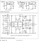
"Monster Bass" reg was the simplistic reg I found in an old audioXpress article on the web (Figure 5, p. 32,). Attached. My initial plan was to build a borbely super shunt, which I am still working on- some parts seem very hard to find though. Especially, Toshibas dual P-channel jfets! The other much simpler circuits worked well but were noisy. The "better" bass performance might have simply been due different current settings, etc. I did not properly compare the two designs side by side.
Please disregard my "lacking bass" comment! I will need way more experimenting time to be able to really say anything about the ikoflexer reg.
Vin-out: 28V-18V (about 5V under recommended)
Current limit about 300mA on both rails (should be a bit more?). Consumption is 50- 250 mA.
Anyway, I am certain that your design is going to shine once it is properly implemented!
🙂
Thank you for the bft92 hint! For the npn, I considered its complementary, the BFR92A. But software simulated about 14V CE voltage in your circuit on Q3. Since it's only rated for 15V ce, it might be a bit dangerous, or?
The reason I go smd, is due to pcb space limitations. Also, I like the idea that all devices are directly touching pcb's traces. In addition, less drills are needed and soldering is super fast.
"Monster Bass" reg was the simplistic reg I found in an old audioXpress article on the web (Figure 5, p. 32,). Attached. My initial plan was to build a borbely super shunt, which I am still working on- some parts seem very hard to find though. Especially, Toshibas dual P-channel jfets! The other much simpler circuits worked well but were noisy. The "better" bass performance might have simply been due different current settings, etc. I did not properly compare the two designs side by side.
Please disregard my "lacking bass" comment! I will need way more experimenting time to be able to really say anything about the ikoflexer reg.
Vin-out: 28V-18V (about 5V under recommended)
Current limit about 300mA on both rails (should be a bit more?). Consumption is 50- 250 mA.
Anyway, I am certain that your design is going to shine once it is properly implemented!
🙂
Attachments
The other much simpler circuits worked well but were noisy.
Hi, did you try also the circuit on the top right in your picture?
The author of that article (which i have too) liked it very much, before going to the more complex version.
Hello! Yes, I did. But only on a solderless proto board. But:
Tonight I am going to etch a proto PCB containing three regulator designs: Ikoflexer's, the one you mentioned and a slightly modified discrete series design found on the web. Also on the board, simple discrete opamp circuits (buffer, high gain) and different cap options. So that I (hopefully) can compare the different reg's sonics. I'll report back after some experiements. 🙂
Best regards!
Christian
That's right, that's the Are Waagbo creation, from this article:
http://www.borbelyaudio.com/pics/waagbo2863.pdf
The grandfather of Salas simplistic 🙂 and great-grandfather of this regulator 😀
Watch out that un-bypassed zener noise.
Looking forward to your report! Thanks for checking it all out!
http://www.borbelyaudio.com/pics/waagbo2863.pdf
The grandfather of Salas simplistic 🙂 and great-grandfather of this regulator 😀
Watch out that un-bypassed zener noise.
Looking forward to your report! Thanks for checking it all out!
I understand that Erno sent him the diagrams. I don't think he designed even the simpler ones, if I read the text correctly. He was just evaluating. Waiting for the new evaluations too bcs he says the simple ones were noisy and I have never made them myself. The Stax is the ancestor, and they even had an old patent. But tubes were there before with radioactive pinkies.
And before tubes was just pen and paper, and before that it was Euclid designing with a stick in the sand... so it all goes back full circle to the Greeks  😀
😀
😀There were other ancients, in the region too. Thracian and Dacian. Spartacus shunted Rome, and others are shunting Ampere.😀
Dear Shunteurs! 😉
I have drawn a PCB layout containing IKO's and Are's regulators as well as my own simplified preamp design featuring two of my own discrete opamps (vertical mount SK99bv mod from the nice SK99b from Soundskultor), bootstrap, servos, etc.. Are' reg is top left, Iko's below, preamp is on the right.
If you have time, please check the regulator PCB designs for errors. Attached is a PNG, which might mot be good enough, there is also a link to the full size 600dpi bmp.
Link: http://www.christianottow.de/Shunt-Reg-Comparison/Shunt shoot out + VV9910 cottow.BMP
25MB size! Server Speed is ok though....
Also, since I am a beginner in all this, some suggestions for good layout would be awesome, too. 🙂
Thanks, best regards
Christian
Attachments
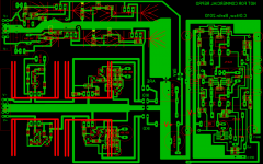
I think you should mount the output capacitor at the very output of the regulator. You have very long traces for Vin and Vout. Since you took the effort to place the preamp on the same pcb as the regulator, you could take advantage of this and make it so that the distance from reg Vout to preamp Vin is not more than 1cm. Possible if you split the two pcbs, and mount the preamp below the regulator, sort of back to back. That's how I'd do it.
I thought that some of the earlier discussion tentatively proposed that locating the output cap at the shunt FET was more likely to give improved stability.I think you should mount the output capacitor at the very output of the regulator.
Maybe I read too much into the opinions that were being posted.
As far as I know this is the original patent
Highly stable constant-voltage power source device
US Patent 4366432 Noro, Masao Stax Ind Ltd
Regards
James
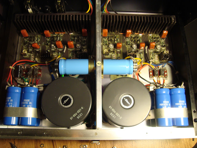
I know I'm a little late to the party here, but here are pics of the original Stax implementation of what they called "super shunt regulation" in my CA-X preamp, for those that are curious (but you're DIYers, of course you're curious!). Yes, that's just the power supply, which looks more suitable for a 100wpc amp. This unit was fixed last year by EchoWars with the help of some guys on here, and I am VERY happy it worked out as the sonics are to die for. Thanks!


Last edited:
Looks very nice! I'm assuming the shunt transistors are on the large heat sinks, what are they? 🙂
Looks very nice! I'm assuming the shunt transistors are on the large heat sinks, what are they? 🙂
yeah, you can just barely see the profile of the three per channel in the middle picture. i will look at the schematics later and see if they specify the transistor. i couldn't get a better picture at the time, unfortunately. because of the way the top cover and upper chassis are designed, the quarters get very tight back there, and it's a major PITA to even access the power supply in the first place. i only opened it up to replace the large cans, and i have no plans of taking it apart again any time soon!
- Status
- Not open for further replies.
- Home
- Amplifiers
- Power Supplies
- My take on a discrete shunt voltage regulator