Here's some food for thought and a reminder. I've been saying that the connection between the regulator and the load should be made with thick, short wires. Have a look at this table of values for 15cm long copper wire of various diameters:
Ga Resist Ind uH Diam mm
22 8.1201 0.1831 0.644
20 4.9951 0.1758 0.812
18 3.1422 0.1687 1.024
16 1.9764 0.1618 1.291
14 1.2426 0.1548 1.628
12 0.7815 0.1479 2.053
10 0.4916 0.0818 2.588
where the fields are the gauge, resistance in milliohms, inductance in mH, and the diameter in mm. So, best case scenario, awg 10 which is 2.588 mm diameter, you still get 81 nH inductance. Right here goes down the drain all the low output impedance you're looking for.
Another issue to consider: is the regulator stability affected the by the wire one uses to connect to the load, and by the ESR of the output capacitor? The answer is yes and yes.
So, for those of you thinking of building this regulator, please keep these things in mind; you cannot simply grab some wire and connect the load. Or you can, but then...
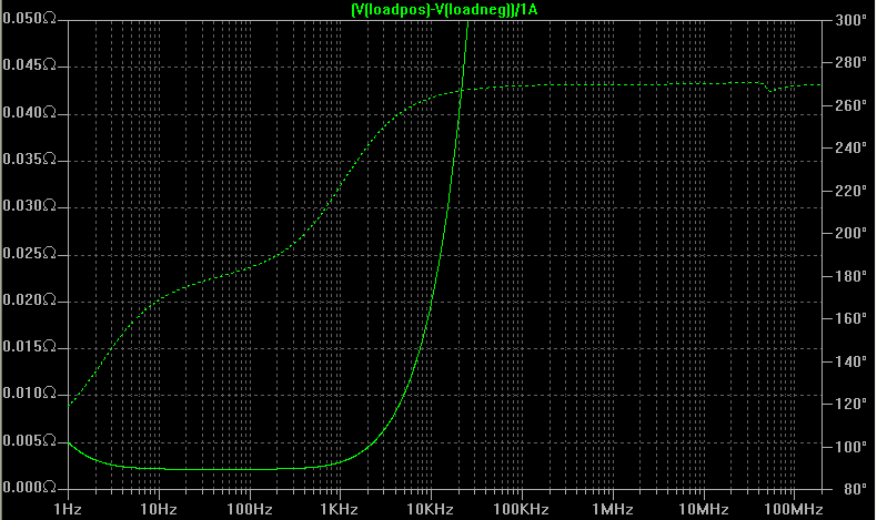
To illustrate what happens, here's an output impedance simulation of the circuit with 15cm long wires (1.5mm diameter) between the regulator and the load. The sense wires are connected with short traces on the pcb, rs- goes to ground, rs+ goes to Vout.
The output impedance looks like this. About 20 milliohm at 10 kHz and 40 milliohm at 20kHz. Gone is the promised sub milliohm output impedance.
In contrast, connecting the remote sense wires (rs- and rs+) directly to the load, AND using a bit of compensation on those wires as well, which I'll talk about later.
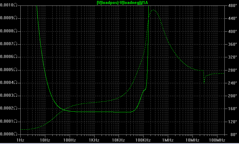
Hi,
if you stack the reg PCB under the load circuit PCB and connect with 1cm (10mm) long wires then most of that good performance comes back.
I recall one Member designing the regulator and the load as a pair so that the two PCBs stacked with just 1mm copper pins joining the PCBs. That was proper integrated design.
Alternatively the load PCB is integrated adjacent to the reg PCB with minimum length traces and the sense traces are brought from between the two circuits and not way back at the regulator active devices.
Here's some food for thought and a reminder. I've been saying that the connection between the regulator and the load should be made with thick, short wires. Have a look at this table of values for 15cm long copper wire of various diameters:
Ga Resist Ind uH Diam mm
22 8.1201 0.1831 0.644
20 4.9951 0.1758 0.812
18 3.1422 0.1687 1.024
16 1.9764 0.1618 1.291
14 1.2426 0.1548 1.628
12 0.7815 0.1479 2.053
10 0.4916 0.0818 2.588
What kind of wire is this? stranded copper?
10 AWG is almost impossibile to find (although i have, from mil surplus).
Check solid core cables, they have much different properties. It is impossible to go under AWG 14, though in that case.
try 0.5mm diameter (cat5) or 0.6mm diameter (solid core hook up wire).
The current capacity of these two diameters is about 3.5A and 5.5A.
There are few places that need any more than that.
The current capacity of these two diameters is about 3.5A and 5.5A.
There are few places that need any more than that.
Andrew, it's true that 0.5mm diameter can take the current, but I was trying to make a different point, not about the current carrying capability of the wire. But about the inductance of different wire sizes (length and diameter). Especially for those who want to build the higher current version of this regulator, they'll have to be very careful with the wire size and for them remote sensing is a must. More inductance in the output wire will affect both the output impedance and the phase margin, which ultimately may lead to oscillations.
Hi,
I am making the same point. Resistance due to small diameter wires is not a big issue. Length of the wires is a much bigger issue.
Compare 10mm of cat5 to 100mm of 2mm diam for resistance and inductance.
I am making the same point. Resistance due to small diameter wires is not a big issue. Length of the wires is a much bigger issue.
Compare 10mm of cat5 to 100mm of 2mm diam for resistance and inductance.
Andrew and Iko, please compare the characteristics of solid core vs multistrand wire - they are very different.
can you refer us to the data for inductance of the multi-stranded with it's inherent larger volume.
Telstar, I was assuming solid core. I can't find much about the inductance of multi-strand or litz wires. Anyone?
It is included only as an illustration of how large the inductance is even with very thick solid wire. It's not a recommendation 🙂
Andrew and Iko, please compare the characteristics of solid core vs multistrand wire - they are very different.
Other than flexibility, I don't think so!
"Litz wire" is a special case, it's nothing like common multi-strand wire and has no place in a "solid core vs multi-strand wire" discussion.
It is included only as an illustration of how large the inductance is even with very thick solid wire. It's not a recommendation 🙂
Why would the wire diameter have any significant effect on a wire's self-inductance?
Also, what about flat conductor? I thought I heard it said around here that flat wires can work better in some situations, because the magnetic field is concentrated around the edges. Don't remember in detail though.
I also thought braided insulated stuff had low inductance, as well as lower noise.
- keantoken
I also thought braided insulated stuff had low inductance, as well as lower noise.
- keantoken
Why would the wire diameter have any significant effect on a wire's self-inductance?
Nice explanation here Inductance of a Straight Wire: A Calculator
kt, I have no experience with flat wires, but there are some calculators online that will give you the inductance, easy to compare them.
Last edited:
Inductance calculations: working formulas and tables
Regards
James
The inductance is not very different from that of a solid wire of about the same diameter as a calipered diameter of the stranded combination, but is decidedly less than that of a solid wire having the same crosss sectional area.
Regards
James
Telstar, I was assuming solid core.
Then, the actual options are limited to awg14, and to a VERY short connection (i.e. the regulator board must be close to the amplifier stage that it will regulate). AWG 12 and 10 solid cores are almost impossible to find and if someone's lucky, very hard to bend.
I can't find much about the inductance of multi-strand or litz wires. Anyone?
I cant find some articles (with some data) I had. I remember that solid core has much lower capacitance, but dunno about inductance 🙁
in the context of cable inductance
As for solid core having lower capacitance. That has almost everything to do with the design of the cable and selection of materials and virtually nothing to do with the number of cores.
compare the characteristics of solid core vs multistrand wire - they are very different.
how do you reconcile these opposite statements?solid core has much lower capacitance, but dunno about inductance 🙁
As for solid core having lower capacitance. That has almost everything to do with the design of the cable and selection of materials and virtually nothing to do with the number of cores.
- Status
- Not open for further replies.
- Home
- Amplifiers
- Power Supplies
- My take on a discrete shunt voltage regulator