I see you used the Corcom power entry modules with the fuses, voltage selector, line filter and croissant warmer tray.
Seriously, very tasteful and well executed. I haven't yet got up the nerve to use wood as a structural enement in an amp chassis but those inserts look secure. I have a few sizes of them in my fastener box I'm sure... Zebrawood (or bocote?) over eastern maple?
Yup, the one on the left is Bocote (excellent guess!)....it still needs a few more coats of lacquer, and the one on the right is pao ferro. The amps are tiger rosewood. Since you need a tiny amount of wood for the project, the exotic stuff is very affordable. If you glue up a substrate, any of the species above cost less than $12 to do a pair of amps. I started out with "finserts" but found that they pulled out rather easily, especially in end grain. The ones shown screw in. If anybody wants Mcmaster P/N's for the feet, rivets, inserts, etc just ask.
Oh yeah, I like that power entry module too! 🙂 Where do I find those? I can find the Corcom with everything but the voltage selector at Mouser.
The power entry modules came from some scrapped prototype medical devices......They do have all of the bells and whistles including line filter. I ended up with a dozen of them from some breast biopsy devices. IIRC they are Schurters and sell for about $70/ea at Digikey/Mouser, so they are not something that I would actually buy........My biggest requirement for power entry modules (besides bells/whistles) is that they have screw hole mounting, as the snap-in kind tend to also snap out easily unless you get the cutout tolerances right. The ones with filters suck up a lot of space under the hood also.
That really is a fantastic job Boywonder! I wonder if you might throw up some internal shots of your work as well?
Also, do you have a good source for the bias adjustment setup you used?
Sure....the internals are not nearly as stylin' as the outside, but I'll post some pics of the underside at the risk of embarrassing myself 😱 It will be clearly obvious that I'm an ME and not an EE.
The bias setup is pretty cool, I'll post some shots of that as well when I get home tonite. The bias pots are Bourns 10 turn WW that I picked up used on Ebay.
Last edited:
Johan
I just wanted to see if the switch to the ECC88 opens up any doors for triode use. If the only viable option is the EF86 in pentode than that shall be the end of the story. BTW, a CCS on the triode anode is acceptable to me if the results would prove better than the EF86 in pentode mode.
I had other requests for a triode input stage (am still wondering why folks prefer a triode there?)
The options for that are endless. As I presumed that these will be monoblocks there would not be advantage from a twin triode input (as in one/channel). I will now give another option for EF86 use viz grid leak bias, as well as both cathode and grid leak bias for my preferred input triode for the triode addicts, the 6GK5.
[Grid leak bias is particularly suitable for sharp cut-off tubes. A large input grid resistor (10meg - 20 meg) causes a very small leakage (or rectification) grid current to flow, giving about 0,5V - 1V negative potential on G1. Advantage is that no cathode resistor is required. Leaving G1 with optimum class-A bias, distortion is somewhat lower than with cathode bias. Disadvantage is that the input source MUST have a low output impedance, typically no higher than a few K.ohm. Otherwise distortion increases to twice that obtainable with cathode bias,]
EF86 (grid leak bias)
The circuit is as before except that R10 becomes 10 megohm and R14 = 560K. The previously added 1,5 megohm from EF86 pin 1 to common falls away. This will keep the ECC88 cathodes voltage at about the chosen 85Vdc. R15 as a cathode bias resistor falls away - but we need a resistor there for gNFB purposes. For that let R15 then be 18 ohm. Obviously an input capacitor is now required to isolate the small negative dc bias on G1. C10 could be 220nF polyester, and must be mounted as close as possible to pin 9 to avoid stray pick-up by G1. Then:
R10 = 10 megohm
R13 = 100K
R14 = 560K
R15 = 18 ohm
R17 = 1,5K (for about 20 dB gNFB)
Input signal = 400 mVrms
This gives an open-loop gain of 870 for my test circuit, with the high frequency -3dB point at about 40kHz.
6GK5 (cathode bias)
R13 = 100K
R15 = 410 ohm (2 x 820 ohms in parallel)
R17 = 22K (for about 20 dB gNFB)
Input signal = 600 mVrms
This gives an open-loop gain of 570 and -3 dB h.f. point of about 80 kHz. (One has the previously mentioned very low grid-plate capacitance and low plate impedance of the 6GK5 to thank.)
6GK5 (grid leak bias)
C10 = >220 nF (as mentioned above)
R10 = 10 megohm
R13 = 100K
R15 = 18 ohm
R17 = 1,2K (for about 20 dB gNFB)
C13 = in vicinity of 1,8 nF
Input signal = 530 mVrms
Open-loop gain is 667, with the -3 dB h.f. point an incredible 170 kHz - a designer's dream for ease of handling gNFB phase shaping.
If not said before, R12-C11 will change with every circuit. They are best left off to start with and figured out when testing, to give minimum square wave overshoot (if necessary at all).
As also said, these are 'chopping-block' suggestions. Especially those with spectrum analysis facilities could suggest improvements
What luck!😱
How about "Orion 88". I'll need to search on that one!
I give up!

Orion® Car Audio - Amplifiers | Subwoofers | Coaxial Speakers | Component Speakers | Sub Enclosures | Accessories
So my next choice was Paganini 88. NOPE, too late.............Grrrrrrrrrrr.
Last edited:
I give up!
So my next choice was Paganini 88. NOPE, too late.............Grrrrrrrrrrr.
You are discovering the futility of using such a well-warn theme. The low hanging fruit has already been picked. You will probably need to find a very creative theme first, then be extra creative when exploring its options.
And don't depend on your own mind for creativity. Use a combination of tools like Google searches, language translators, irrational associations.
..Todd
I still vote for Adagio88. At least at this point there is no commercial interest so it shouldn't be a violation of anything.
I still vote for Adagio88. At least at this point there is no commercial interest so it shouldn't be a violation of anything.
I agree. Thorsten Loesch called his DAC Adagio, too. There is no big deal there, it's a private project and you want a name. Call it Adagio.
If you want to make everything water proof, write the folks over at Art Audio, I bet they won't mind. Say it's a private project only, perhaps mention that your audio community disputed over it, then they know that being petty there is just gonna do them bad. 😉
I still vote for Adagio88. At least at this point there is no commercial interest so it shouldn't be a violation of anything.
Well, I think the spirit of what you suggest is probably correct, in that there's nothing to really be concerned about.
Having said that, it's important to understand that trademark laws are not really concerned with competing commercial interests. They exist to protect brand exclusion in order to prevent market confusion. If the original Adagio tube amp people think our project will cause brand confusion, they can legally defend their brand (force us to change the name). But I don't think they would have any reason want to do that (unless someone began a marketing campaign for this project.)
Another entirely subjective comment: I think the classical music theme has been milked to death and is sounding pretty cliche' these days. (But it's not something I am losing any sleep over.) 🙂
..Todd
Last edited:
Having said that, it's important to understand that trademark laws are not really concerned with competing commercial interests. They exist to protect brand exclusion in order to prevent market confusion. If the original Adagio tube amp people think our project will cause brand confusion, they can legally defend their brand (force us to change the name). But I don't think they would have any reason want to do that (unless someone began a marketing campaign for this project.)
I don't know what those in the Land Of The Free do, but here in Germany it's common practice for lawyers to search for trade mark violations, because they can live of the fees for those warning notes. I know a lot of cases where the victim of this practice was a private person using a name for fun. You can even get pricey warning for using an ebay name remotly related to an established trademark.
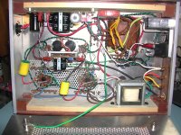
what I did on my summer vacation.......
Here are a few shots of the underside.....Hopefully more fuel for chassis build ideas.....The B+ PS and (most of) the bias supply is on perfboard mounted to the side panel; the small toroid is the bias transformer.
In general, power stuff is on one side, and signal stuff is on the other.
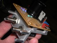
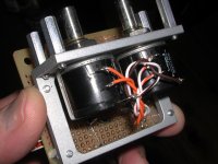
Bias bracket (my favorite part) is a piece of plain vanilla 1" x 1 1/2" x 1/8" thick aluminum angle with some small standoffs to get the end of the shafts flush with the top deck. The perfboard on the bracket holds the final filter cap and R's for the bias supply, as well as the 10M45S, adj pot etc. for the driver stage.
I ran out of room on the PS perf board so that's what drove the angle bracket for the bias pots. The angle bracket allows mounting another board vertically without any additional holes in the top deck. Two of the mounting holes for the bracket also hold one side of the 6GK5 sockets, further reducing fasteners.
I milled the AL angle for extra coolness, but it would work fine with just the holes for the pots and the standoffs.
I would have done an amperite based turn on delay but I don't have the room for a separate heater transformer, another socket and relay....
The amps are Poindexter's 6GK5/EL34 music machines.
I wonder if you might throw up some internal shots of your work as well?
Also, do you have a good source for the bias adjustment setup you used?
Here are a few shots of the underside.....Hopefully more fuel for chassis build ideas.....The B+ PS and (most of) the bias supply is on perfboard mounted to the side panel; the small toroid is the bias transformer.
In general, power stuff is on one side, and signal stuff is on the other.
Bias bracket (my favorite part) is a piece of plain vanilla 1" x 1 1/2" x 1/8" thick aluminum angle with some small standoffs to get the end of the shafts flush with the top deck. The perfboard on the bracket holds the final filter cap and R's for the bias supply, as well as the 10M45S, adj pot etc. for the driver stage.
I ran out of room on the PS perf board so that's what drove the angle bracket for the bias pots. The angle bracket allows mounting another board vertically without any additional holes in the top deck. Two of the mounting holes for the bracket also hold one side of the 6GK5 sockets, further reducing fasteners.
I milled the AL angle for extra coolness, but it would work fine with just the holes for the pots and the standoffs.
I would have done an amperite based turn on delay but I don't have the room for a separate heater transformer, another socket and relay....
The amps are Poindexter's 6GK5/EL34 music machines.
Attachments
I don't know what those in the Land Of The Free do, but here in Germany it's common practice for lawyers to search for trade mark violations, because they can live of the fees for those warning notes. I know a lot of cases where the victim of this practice was a private person using a name for fun. You can even get pricey warning for using an ebay name remotly related to an established trademark.
I would imagine that inquiring about using the Adagio trademarked amp name "just for fun" and "not for commercial use", etc. would quickly generate a cease-and-desist letter from their attorney.
This assumes that they have successfully trademarked the name for tube amp use.
Doing a quick search at the US patent & Trademark web site returned 65 hits for "adagio" as a trademark.
EDIT: Crestron Corporation has adagio trademarked for the audio amplifier field of use, I didn't find anything registered for the SET tube amp company, but I didn't look very hard.
Last edited:
I don't know what those in the Land Of The Free do, but here in Germany it's common practice for lawyers to search for trade mark violations
It is common here too. I received one of those warning notices because a company whose name and product I won't mention (Google sees all) had a person running Google searches weekly looking for anything that resembled their trademark. It seems that someone left out the space between Simple and SE on this forum in a post about my Simple SE board. That combination of letters is the name for one of their home theater boxes, which is an audio product. They were prepared to defend their "well developed" trademark against infringement by another audio product even though I was not the originator of the misspelling. I had copied and pasted it in other forum posts which made me look guilty. We agreed that I could use the common words "Simple" and "SE" (can't trademark those) but I could never stick them together, and I had to warn any other people referring to my product not to do the same.
So we know that there are "defenders of trademarks" out there using Google and other search engines. We know that Google finds these forum posts. So it is possible that someone owning a registered trademark, or even an implied mark may feel threatened by what they find via Google. I try to use combinations of common words for names, or simple letters. My KT88 project is known as the BFA-88. Trademark that!
In reality it is very doubtful they would waste their time going after you. They might send you a scary letter, but the chances of them paying for a litigation against someone with little or no resources is fairly slim.
That said, it's probably not worth the trouble. Do like open source software does...come up with a completely obscure name, rather than a clever one. Like Blowfish or Spidermonkey.
That said, it's probably not worth the trouble. Do like open source software does...come up with a completely obscure name, rather than a clever one. Like Blowfish or Spidermonkey.
That Bias pot mount is excellent as is all your chassis work! I'm taking some of these Ideas.
Regarding those first cases you posted. I may have come up with a cheap way to replicate them. Follow me on this.
Obtain an appropiate sized hammond case. Cut the top out with a jigsaw, leaving a lip around the edge to match the one on the bottom. A premade top plate from FPE can now be fastened to the top of the box. wood trim fastened to the sides, and a FPE faceplate fastened to the front.
What do you think?
Even easier would be too just flip the hammond upside down and attach the top plate to what was the bottom lip, leaving the original top of the hamond to become the new solid bottom of the chassis. The problem with that easier plan, is that now the internal connections from the top plate to the rear panel will be tricky to make as there is no access once the top plate gets attached..
They might send you a scary letter, but the chances of them paying for a litigation against someone with little or no resources is fairly slim.
The facts of litigation were carefully explianed to me by my lawyer. The first rule is "A lawyer on staff always beats a lawyer on retainer". The second rule is that a lawyer on staff without much to do will find or make a case to justify their job.
I learned this lesson when the city I live in decided that my satellite dish (which was being used for ham radio EME and what would have been my masters thesis) had to go. I pissed the code enforcement nazis off so now they demanded that all antennas (even the flippin TV antenna) be removed from the property within 48 hours or I would be fined $400 per day. There is a federal preemption (PRB-1) that makes it illegal for a local government to do this. They said that I was welcome to challenge them in court, but I would lose and a lien against my house for the $400/day fine would be filed within one week.
After my lawyer explained the facts to me, and how much it would cost to fight city hall, I punted. I have since decided to avoid involving lawyers where ever possible.
The classic difference between being right and winning the case. There is a German saying:
"In high seas and in court your in god's hand."
Over here the lawyers are often doing nothing else then sending these warning letters ("Mahnanwalt"), cause it makes a good living. Without a conscience, the world is yours....
"In high seas and in court your in god's hand."
Over here the lawyers are often doing nothing else then sending these warning letters ("Mahnanwalt"), cause it makes a good living. Without a conscience, the world is yours....
That Bias pot mount is excellent as is all your chassis work! I'm taking some of these Ideas.
Regarding those first cases you posted. I may have come up with a cheap way to replicate them. Follow me on this.
Obtain an appropiate sized hammond case. Cut the top out with a jigsaw, leaving a lip around the edge to match the one on the bottom. A premade top plate from FPE can now be fastened to the top of the box. wood trim fastened to the sides, and a FPE faceplate fastened to the front.
What do you think?
Even easier would be too just flip the hammond upside down and attach the top plate to what was the bottom lip, leaving the original top of the hamond to become the new solid bottom of the chassis. The problem with that easier plan, is that now the internal connections from the top plate to the rear panel will be tricky to make as there is no access once the top plate gets attached..
Your idea would certainly work, and you would not have any wood (=combustible) materials inside the case, which is a good thing. My chassis are not going to get a UL sticker any time soon.
Ignoring labor (ie hobby labor=$0/hr), I'm not sure that you are saving any money, but it will certainly be a faster build. You are still fabbing a top deck, front plate and wood side panels.
Ignoring the zillions of labor hours I have into the chassis, there is probably less than $60 in materials for the pair.
You would also need to transfer the holes in the decorative front plate thru the Hammond chassis, and poke holes in the rear of the Hammond chassis.
I would consider an air chisel with a split point tip to cut the top of a hammond chassis out, it may be faster and cleaner. You also have to figure out how to fasten the wood to the sides. I suppose with thick enough wood, you could just screw from the inside.
In honor of all Johan's work, how about the Pretoria88? Sahara88?
Not bad. I think your new theme is excellent.
..Todd
I'm not sure I understand? . Are you saying the PS will produce 288v as is? Are the other voltages correct?
Sorry Tubemack, missed this one.
I referred to the TAJ drawing(s), where the power supply schematic has not changed. I used a 460V supply at point "12AT7 B+" feeding the LTP and retained R2 = 68K on all the tests, feeding the first stage. The indicated voltages existed under these conditions. As circuits changed somewhat, the voltage over C6 changed slightly (always around 300V) - not to worry. The very first circuit, also with the same power decoupling chain, had the wrong voltages indicated, i.e. they could not exist with R2 etc. having been what they were.
By the way, C6 is far to small to my mind. There is no exact way to calculate the value, but with modern capacitor development one could easily fit 16µF there. I would suggest 32µF 460V; they are not very big physically and can only improve l.f. decoupling.
- Home
- Amplifiers
- Tubes / Valves
- Mullard 5-20 KT88 PP blocks!