Vdif= U1*sinus ω(t+0)- U2*sinus ω(t+ α)*β
Sine of the angle α is a function of the reciprocal of the reserve strengthening Au* - Au
Sine of the angle α is a function of the reciprocal of the reserve strengthening Au* - Au
Isn't it little bit purposeless mathematics? Which is practical impact into your statement?
If you do not know mathematics, so you must prepare amplifiers trial - error
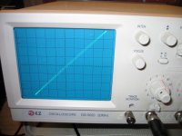
FYI (For Your Information) - the measured result at 100kHz (I am attaching it again) and the simulation result at same input voltage are completely different. You are saying that simulators do not make mistakes, but they are only as good as models used. If you want to live in a virtual world only, then poor models and incomplete maths are perfect for you.
P.S.: as a real world amplifier design is my know how, I will not show the simulation result. Your turn to learn real world design.
P.S.: as a real world amplifier design is my know how, I will not show the simulation result. Your turn to learn real world design.
Attachments
Federmann, doubt about our knowledge, or want to just be blunt and to insult, as in comments on your site ?
Federmann, doubt about our knowledge, or want to just be blunt and to insult, as in comments on your site ?
Mr. Federmann, these images were already here, do you have any other comics?
???
Federmann, don't play innocent...you have many ribaldries on your sites...for example against me...
Federmann, don't play innocent...you have many ribaldries on your sites...for example against me...
This thread is about something else, do not break it again.
Please keep thread
Vdif= U1*sinus ω(t+0)- U2*sinus ω(t+ α)*β
Sine of the angle α is a function of the reciprocal of the reserve strengthening Au* - Au
About something else ? Yes Federmann...about man, which desperate publicity and glory, 'cos he's convinced of own personal charisma....
t is time, α is angle, β is constant
Vdif= U1*sinus ω(t+0)- U2*sinus ω(t+ α)*β is mathematically incorrect
If you do not know mathematics, so you must prepare amplifiers trial - error
Vdif= U1*sinus ω(t+0)- U2*sinus ω(t+ α)*β is mathematically incorrect
If you do not know mathematics, so you must prepare amplifiers trial - error
Last edited:
t is time, α is angle, β is constant
Vdif= U1*sinus ω(t+0)- U2*sinus ω(t+ α)*β is mathematically incorrect
If you do not know mathematics, so you must prepare amplifiers trial - error
No worries, simple math, simple formula. Who knows what we are talking, knew the correct results. He who can not use the correct values, the correct result will never know.
You must prepare amplifiers trial - error .
No worries, simple math, simple formula. Who knows what we are talking, knew the correct results. He who can not use the correct values, the correct result will never know.
The formula is incorrect, you cannot add time t and angle a. Either use both time or use both angle.
Also, it is not clear what you mean by U1 and U2. It seems that U1 is the peak input voltage, and U2 is the peak output voltage. Is that what you mean?
jd
Do you have any new findings please?
I could post detailed graphs, but I'm not sure what I'm looking for or why. What I do know is that while the NTP is anything but linear, it is very fast and more stable - so using the NTP with higher OLG might reasonably compensate for any extra nonlinearity while being just as stable as an LTP amplifier.
But I'm still not sure what I'm looking for, and how these graphs relate to the modulation while in the nonlinear region.
- keantoken
No worries, simple math, simple formula. Who knows what we are talking, knew the correct results.
You are teaching others to learn and study mathematics, for the reason to become 'better' circuit designers. Why do not you provide correct and valid mathematical formulae??
Also, it is not clear what you mean by U1 and U2. It seems that U1 is the peak input voltage, and U2 is the peak output voltage. Is that what you mean?
jd
Yes, exactly. U1 is connected to the positive input. β is the transmission of output to the negative input. β is not constant.
Yes, exactly. U1 is connected to the positive input. β is the transmission of output to the negative input. β is not constant.
β is not constant? That's new. Why/how not?
Are you really teaching electronic circuit design?
BTW The formula is still incorrect, you cannot add time t and angle a. But you don't seem to be interested in correctness anyway, right?
jd
You are teaching others to learn and study mathematics, for the reason to become 'better' circuit designers. Why do not you provide correct and valid mathematical formulae??
The formula is correct. No worries.
β is not constant?
Are you really teaching electronic circuit design?
jd
Yes he does, look here and find Bohumil Federmann:
S©IEØ - Ro¾nov pod Radho¹tìm
The formula is correct. No worries.
No. There is an error in units. It is wrong, anybody with 1st grade algebra can see that. Can you?
Ohh, I forgot. You're not interested in correctness....
jd
- Status
- Not open for further replies.
- Home
- Amplifiers
- Solid State
- Influence of the delay amplifiers for listening characteristics