Make amplifier transfer characteristic, x = input voltage, y = output voltage i...
Shape characteristics of a lot to say.
I ask all who can disclose any amplifier. Measured or simulated.
Thank you all.
Bobby
Please be careful that, you damage the amplifier. May be lower than the frequency of 100kHz.
Last edited:
I know, so I wrote:
Vdif might not exactly, but to have an idea that's enough.
.
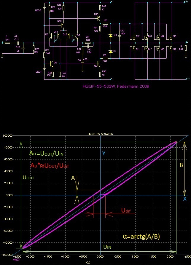
Blue, oblique line is the ideal transfer characteristic. There Vdif = 0 Actual characteristic is brought to the feedback divider. Deviation from the blue line shows the voltage does not represent the phase relationships when the capacity is used, etc.
A measurement like this, Federmann? This was to reveal the output impedance.
I believe that the discovery of the output impedance is not enough.
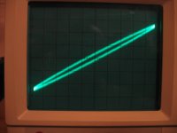
I asked to know what kind of a plot you require (Lissajous). No problem to measure tomorrow at 100kHz Vout/Vin, my amp handles 100kHz without any problem.
BTW, the plot shown was MOSFET amp with error correction, output forced by current. X - current, Y - voltage at output terminals.
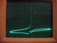
Just for fun, this is a power opamp, OPA549:
BTW, the plot shown was MOSFET amp with error correction, output forced by current. X - current, Y - voltage at output terminals.
Just for fun, this is a power opamp, OPA549:
Attachments
Last edited:
Please don't confuse the issue, Bob. We all know your opinions on the subject. You will also find that most video amps with the same basic topology as Scott Wurcer's AD797 have MUCH higher open loop bandwidths. Could the be because of the need to linearize the input diff pair, and the advantage (for some reason) to have a high open loop bandwidth, perhaps for minimum differential phase?
John,
I am not confusing the issue at all. You just keep bringing up stuff about PIM that was settled long ago, not in favor of the need for large open loop bandwidth to avoid PIM. For feedback-generated PIM, it is the movement of the closed loop pole that creates PIM. The closed loop pole movement is relatively independent of the open loop bandwidth. You should know this. For a refresher, read my PIM paper on my site at Cordell Audio: Home Page. The math and the amplifier measurements there make the point.
Merry Christmas,
Bob


?
Silence ?
I can hear it from here 🙂
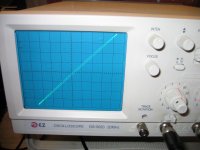
Real world measurements... you can't beat 'em 😉
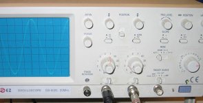
7.8 V output voltage for 4Ω and 100kHz? Is about 16W. Nice result. Angle α is arctg 2 / 38 = approximately 3 °. Is an excellent result. Vdif = approx 10mV, excellent result. Moreover, these topology, which has a better course Vdif.
My compliment!
How would it look for full performance?
How does simulation? Is similar?
My compliment!
How would it look for full performance?
How does simulation? Is similar?
The X and Y scales of the scope are calibrated.
But, I still fail to see any relationship between this measurement and distortion and subjective sonic results. For example, this amplifier has JFET input stage. As you know, the linear part of the transfer characteristics of the JFET differential stage is much wider than that of the BJT, but Gm is lower. How would you generalize your 'Vdiff results' ?
But, I still fail to see any relationship between this measurement and distortion and subjective sonic results. For example, this amplifier has JFET input stage. As you know, the linear part of the transfer characteristics of the JFET differential stage is much wider than that of the BJT, but Gm is lower. How would you generalize your 'Vdiff results' ?
Regarding Federmann's concerns of 100kHz frequencies in audio signal etc. - the worst case with highest RF content I have ever measured is the SACD DSD ultrasound noise, which rises fast above 30kHz. This noise is much higher in amplitude than any musical instrument ultrasound components recorded anywhere. An example of the DSD noise is attached (voltage and time scale shown in the image), and it is present despite the obligatory 50kHz low-pass at the SACD player output :
Attachments
- Status
- Not open for further replies.
- Home
- Amplifiers
- Solid State
- Influence of the delay amplifiers for listening characteristics