only if you build a back up power station for the times when the wind is too low or too high.windmills😀
You also have to limit the proportion of unswitchable power from windmills to prevent overvoltage at times of low demand. Power companies will not volunteer to turn off their expensive windmills just because we have all gone to bed.
Ireland had to place a moratorium on all proposed windmill power until the industry came up with a solution to this overproduction of energy during times of low demand.
Last edited:
Which is type of input transistors, Ovidiu? ROHM's?
Hitachi 2SC2547/2SA1085. The Rohm devices are practically equivalent.
There's a thread about HPS4.x http://www.diyaudio.com/forums/analogue-source/154394-hps-4-0-phono-stage.html
Thank you, Ovidiu, it's great, I have still several hundreds these Hitachi's... 🙂. Only little question: OPA552 don't need balanced Rg at inputs for lowest distortion ? And little notice: by my experiences, bjt and fet have never the same sound, but maybe in this case yes, thanks to RIAA correction....very nice work.. 
Syn08, I have to say you really know how to make a compact PCB. Looks very good - no doubt sounds great too. Nice result!
Thank you, Ovidiu, it's great, I have still several hundreds these Hitachi's... 🙂. Only little question: OPA552 don't need balanced Rg at inputs for lowest distortion ? And little notice: by my experiences, bjt and fet have never the same sound, but maybe in this case yes, thanks to RIAA correction....very nice work..
I'm not sure about what you mean re: OPA552 and Rg. I also think HPS4.1 will sound different to HPS3.1 and I'm really excited about doing some listening tests. Sometimes next week, after the Christmas dust settles 😀 I have to drill the steel case.
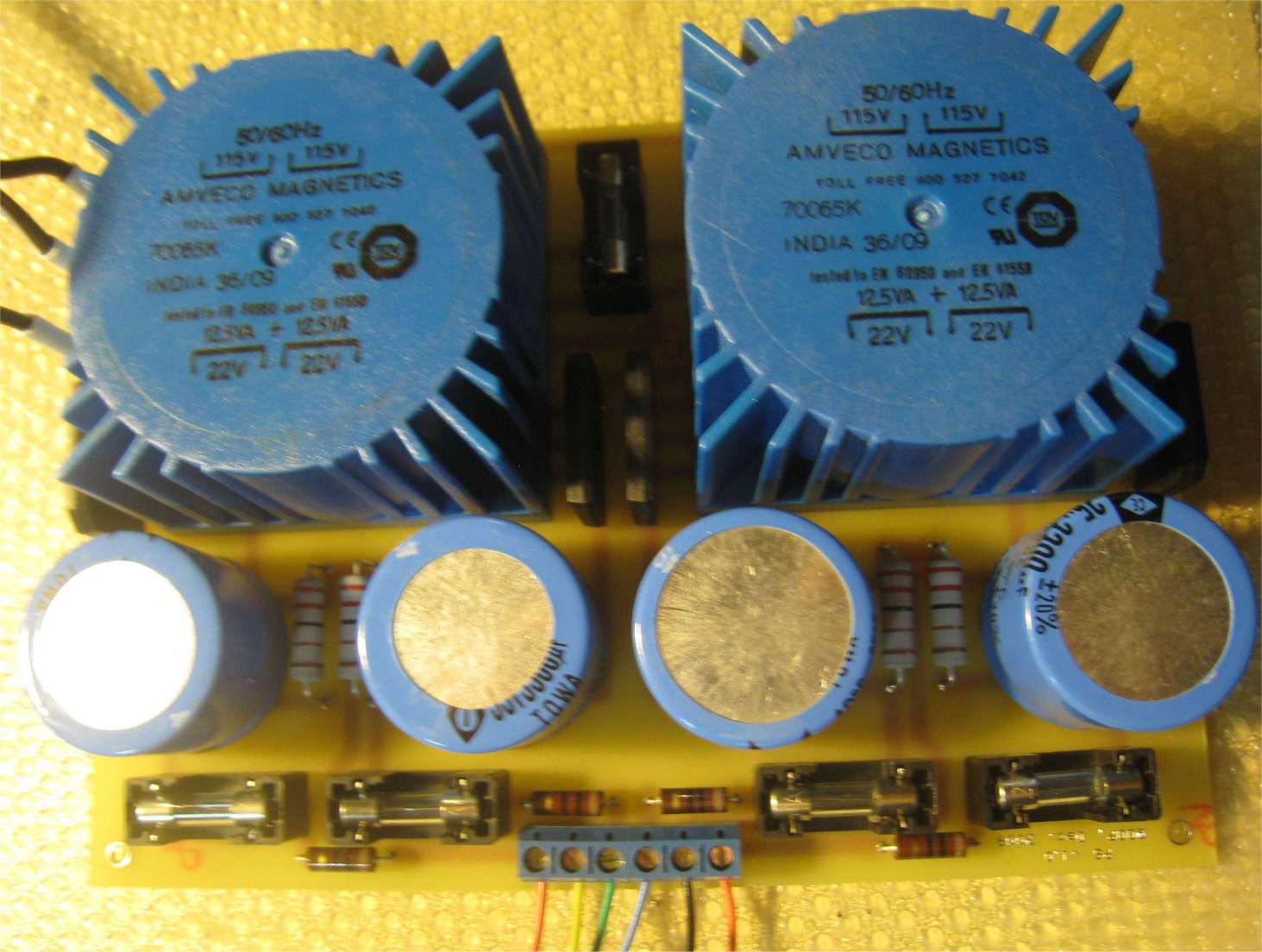
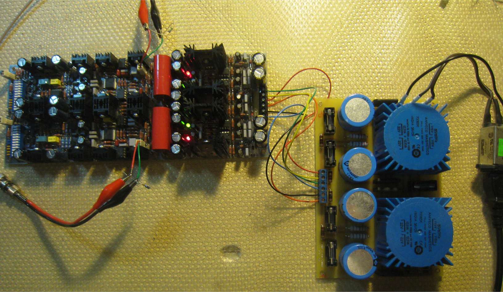
Meanitme, I have decided to do a PCB for the raw power supply (rather than using perf board and wiring as in HPS3.1). See the attached pictures.
Testing went very well, 0.28-0.3nV/rtHz and 0.008% distortions at all frequencies and output levels up to 40Vpp. I also got only 25uV output hum (input shorted), before even throwing everything in the steel case. This is an excellent level, equivalent to 2.5nV input hum. It's actually a little better than HPS3.1 in the same stage (before case), probably because of a better layout of the input stage. But the key to low hum is the dual mono construction and the ground loop(s) handling, as described on my web site under "wiring".

Rg = " resistance ( output impedance ) " of generator...some opamps need for lovest distortion the same impedances at both inputs...
Here is a photo of my first DIY - AMP, Carlos' DXAMP.
Driven by 2 torroids with 160 watts each, a soft-power-on circuit, a slightly modified version of Greg's PSU, Carlos' PCBs with SANKEN
transistors and speaker protection circuits (so the speakers do not "plopp" during PowerOn/-Off any more).
It looks a little bit chaotic inside with all the wires running front to back and since I did not find an ALU chassis I built one out of MPX.
But looks doesn't matter to me.
This amp rocks and sounds divine.
Best regards - Rudi_Ratlos
An externally hosted image should be here but it was not working when we last tested it.
Driven by 2 torroids with 160 watts each, a soft-power-on circuit, a slightly modified version of Greg's PSU, Carlos' PCBs with SANKEN
transistors and speaker protection circuits (so the speakers do not "plopp" during PowerOn/-Off any more).
It looks a little bit chaotic inside with all the wires running front to back and since I did not find an ALU chassis I built one out of MPX.
But looks doesn't matter to me.
This amp rocks and sounds divine.
Best regards - Rudi_Ratlos
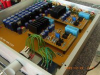
Very Nice metal-work and PCBs HKC.
On picture two it looks like the cooling fins are too high...is it an optical illusion or..?
On picture two it looks like the cooling fins are too high...is it an optical illusion or..?
Last edited:
Very Nice metal-work and PCBs HKC.
On picture two it looks like the cooling fins are too high...is it an optical illusion or..?
Hi Nrik
The fins are just about 3mm distance from the top plate.
szekeres headphone amp
just finished my szekeres-based desktop headphone amplifier with active ccs and expanded l.f. response... (my first completed amplifier!) webpage with info is here: geekysuavo.org/lassie.
~ brad.
just finished my szekeres-based desktop headphone amplifier with active ccs and expanded l.f. response... (my first completed amplifier!) webpage with info is here: geekysuavo.org/lassie.
An externally hosted image should be here but it was not working when we last tested it.
~ brad.
HKC, where did you get your enclosure? Self made or did you buy it in?
Very nice looking project!
Very nice looking project!
HKC, where did you get your enclosure? Self made or did you buy it in?
Very nice looking project!
Hi Bonsai
I designed the case to fit the pcb and custom order from a manufacturing house in China. It is made of 6061 Aluminum.
Best Regards
Gary
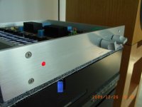
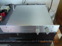
HPS 4.1 is ready
Before closing the lid:

A new box installed in the phono stack, ready for listening tests.

All I can tell so far: after 108dB of gain at 60Hz, zero hum, ear on grille on my 97dB horns. And also zero hiss.
Before closing the lid:
A new box installed in the phono stack, ready for listening tests.
All I can tell so far: after 108dB of gain at 60Hz, zero hum, ear on grille on my 97dB horns. And also zero hiss.
HKC, can you tell us who the manufacturing house is?
Hi Bonsai
Sure, can I send you the information through private message or e-mail?
syn08 : I tried to find the thread where you 'bragged' about your new circuit, but I couldn't find it. Would you...?
syn08 : I tried to find the thread where you 'bragged' about your new circuit, but I couldn't find it. Would you...?
http://www.diyaudio.com/forums/analogue-source/154394-hps-4-0-phono-stage.html
- Home
- Amplifiers
- Solid State
- Post your Solid State pics here