My lightly modified Cambridge Audio Azur 340A SE 😀 😀 😀
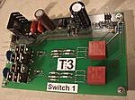
Now dual mono Naim poweramps with dual Avondale audio minicap6 PSU's. 2 x 225VA trafos. Dual mono SKA audio SKpre class-A preamps running on TeddyReg's. Relay input switching from Dantimax.dk, Alps motorpot. Everything works off the original Cambridge audio front panel pcb so I have the full function of the front panel buttons and remote. No tone or balance any more though....
Its still not completely finished but Ive had it running. Sounds v nice and should be even better with a few more small tweaks. Thinking of adding a pair of separate transformers and filter caps for the preamp section. They currently piggyback off the main amp supplies.
EDIT: Apart from the case and front panel control PCB I have re-used the AC main's inlet and switch (left rear corner of photo), and re-cycled the original output relay. This connects to the front panel PCB and gives me a muted 3 second delay on switch on to allow the amps to settle. So no pops or thumps when I switch on. And I have full remote function with the original remote.
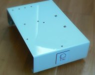
I'll be filling in the unused holes for the balance/tone-control's and headphone/ipod sockets. Then I'll be respraying in automotive high gloss metallic paint. Probably in black. I hope to have the front panel professionally engraved at some point to identify the input buttons and power switch.
Now dual mono Naim poweramps with dual Avondale audio minicap6 PSU's. 2 x 225VA trafos. Dual mono SKA audio SKpre class-A preamps running on TeddyReg's. Relay input switching from Dantimax.dk, Alps motorpot. Everything works off the original Cambridge audio front panel pcb so I have the full function of the front panel buttons and remote. No tone or balance any more though....
An externally hosted image should be here but it was not working when we last tested it.
Its still not completely finished but Ive had it running. Sounds v nice and should be even better with a few more small tweaks. Thinking of adding a pair of separate transformers and filter caps for the preamp section. They currently piggyback off the main amp supplies.
EDIT: Apart from the case and front panel control PCB I have re-used the AC main's inlet and switch (left rear corner of photo), and re-cycled the original output relay. This connects to the front panel PCB and gives me a muted 3 second delay on switch on to allow the amps to settle. So no pops or thumps when I switch on. And I have full remote function with the original remote.
I'll be filling in the unused holes for the balance/tone-control's and headphone/ipod sockets. Then I'll be respraying in automotive high gloss metallic paint. Probably in black. I hope to have the front panel professionally engraved at some point to identify the input buttons and power switch.
Last edited:
Hi Mike,
very well laid out, obviously very well planned.
It looks factory assembled. A credit to the DIY enthusiast.
very well laid out, obviously very well planned.
It looks factory assembled. A credit to the DIY enthusiast.
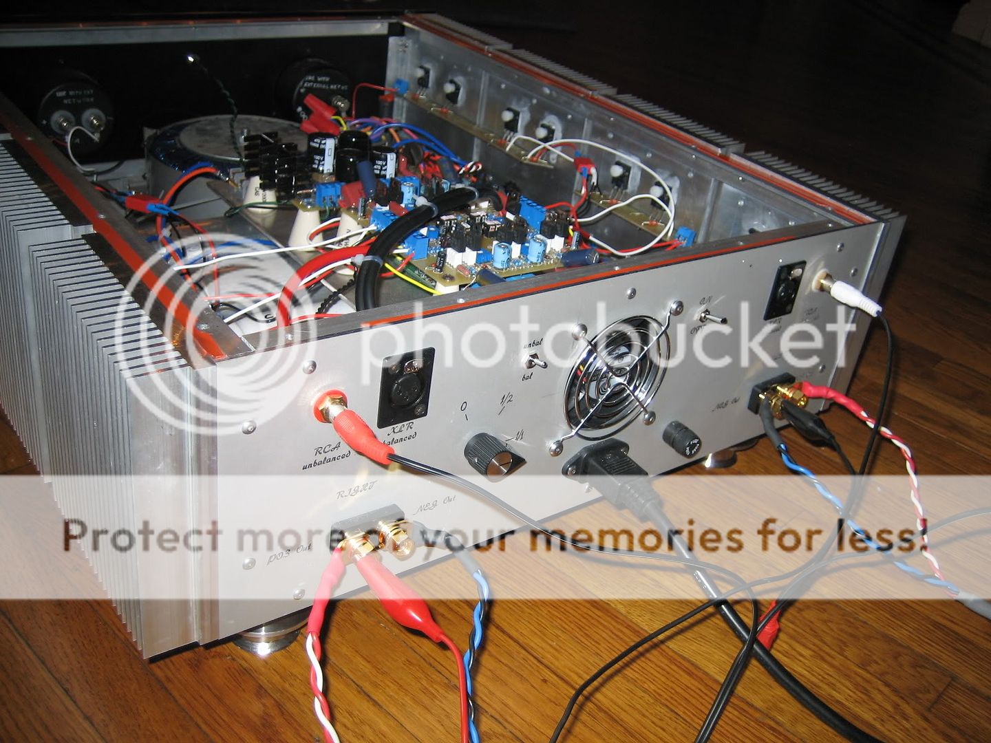
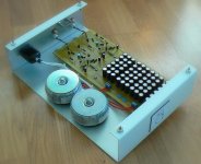
Another pic from the other side...
I need to build a more robust PSU for the input-switching/control circuitry, this will mount on the side panel on the left so needs to be as low profile as possible. Also considering adding another smallish trafo and psu (30-40VA) for the preamps. I would need to squeeze it in the space in the rear near the AC inlet (front right corner of photo).
Need to think it over a bit first.
Attachments
Last edited:
Now that we have a gallery, I imaging the best way to get the benefits of both threaded discussion and ease of browsing is to post images to the gallery and then link to the gallery pictures from within this thread. As time allows I'll write an importer script to pull all the images out of this thread, put them in the gallery (marked as uploaded by each member), and replace the links in the thread with links to the gallery images. Might be biting off more than I can chew but that would be the ideal solution right?
Let me know what you think! 🙂
Let me know what you think! 🙂
Member
Joined 2002
Now that we have a gallery, I imaging the best way to get the benefits of both threaded discussion and ease of browsing is to post images to the gallery and then link to the gallery pictures from within this thread. As time allows I'll write an importer script to pull all the images out of this thread, put them in the gallery (marked as uploaded by each member), and replace the links in the thread with links to the gallery images. Might be biting off more than I can chew but that would be the ideal solution right?
Let me know what you think! 🙂
Jason,
are we able to use the img feature from the gallery into posts ? will this eat up more bandwidth ?
Jase
my opinion.
Hi,the little pics should remain in the thread.
The big images could usefully be downloaded on demand.
The thread can contain a short description.
I think all discussion should have a discussion thread link.
Hi,the little pics should remain in the thread.
The big images could usefully be downloaded on demand.
The thread can contain a short description.
I think all discussion should have a discussion thread link.
Jason,
are we able to use the img feature from the gallery into posts ? will this eat up more bandwidth ?
Jase
Yes, you can use the IMG feature from the gallery to put images into posts. In fact when you're viewing an image in the gallery there are BBCode links already preformatted for you so you can just click, copy, and paste (see attachment). Pretty cool!
The thread can contain a short description. I think all discussion should have a discussion thread link.
Do you mean This (real) "thread" or the "comments" that you can post to a picture? When you say "all discussion should have a discussion thread link" can you give some more detail?
Attachments
I commented on a wiring error posted in the pics thread.
It became a discussion on wiring up the Safety Earth. That comment of mine and the discussion that followed should not have been the the pics thread.
Each pic could usefully have a short description so that we builders can see what we are looking at.
All discussion on the project should NOT be in the pics thread.
Yep, gotcha! All gallery images of pictures that are related to projects should have a link from the pic to the project.
One the things that will emerge from our information reshuffle over the next few months will be the labeling of projects with a unique tag so it's easy to link articles, threads, images, and other information on a single project all together. Baby steps...
One the things that will emerge from our information reshuffle over the next few months will be the labeling of projects with a unique tag so it's easy to link articles, threads, images, and other information on a single project all together. Baby steps...
Big chance to show off
I built this a couple years ago. It's a Pass A75. Pretty standard except the VU meters (Scales are in German) and the chassis. It was built for and now lives with my German buddy in Florida in a well air conditioned living room.
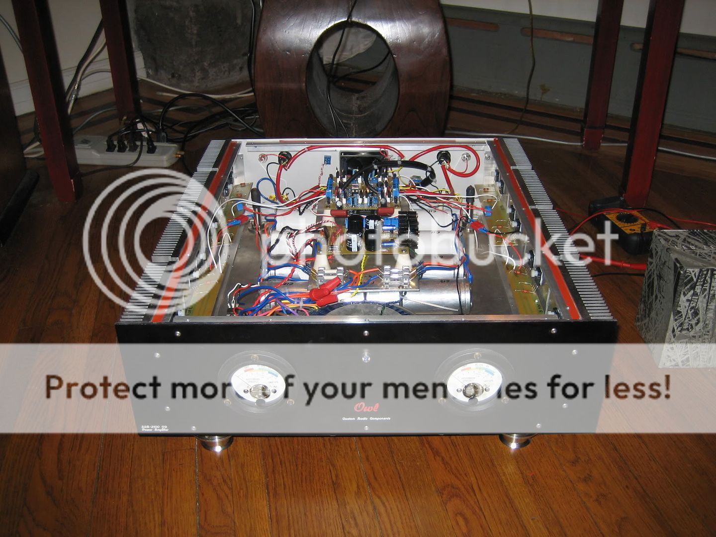

I built this a couple years ago. It's a Pass A75. Pretty standard except the VU meters (Scales are in German) and the chassis. It was built for and now lives with my German buddy in Florida in a well air conditioned living room.
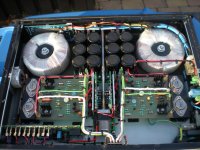
Solid State Speaker Relay
This is one of my current side topics.
A fully isolated solid state speaker relay.
It offers distortion below -120db and is capable to operate even in high power amps in the range of multiple kW and rails up to +/-100V.
Of course it is also very well suited for class D, not only solid state.
And most impressive: Choko went for a proper PCB, instead of his bad attitude of doing everything with P2P wired protos. 😱
Attachments
MRR White serie
Hi There, ( hi destroyer, hi dark horse )
my very last realization !
Gorgeous sound... Amazing dynamic...
Eighty capacitors ( ultra, ultra low ESR )
Class A ( 2 x 7 watts ) with no Heatsink
Yeahhhhhhhhhhhh ...
Have fun
Hi There, ( hi destroyer, hi dark horse )
my very last realization !
Gorgeous sound... Amazing dynamic...
Eighty capacitors ( ultra, ultra low ESR )
Class A ( 2 x 7 watts ) with no Heatsink
Yeahhhhhhhhhhhh ...
Have fun
Attachments


Very nice Rockmandrake..... lovely amplifier
Beautifull circuit, wonderfull colour, nice shape.
Great!
Carlos
Beautifull circuit, wonderfull colour, nice shape.
Great!
Carlos
Do we make audio amps here or nuclair plants?
what a power on this page.
I am making a pcb for the topamp, on demand, but I loose the email adres of this guy.
if he is here pleas mail me.
regards
what a power on this page.
I am making a pcb for the topamp, on demand, but I loose the email adres of this guy.
if he is here pleas mail me.
regards
kees52: " Do we make audio amps here or nuclair plants? ... what a power on this page. ..."
Hopefully some of you guys are doing both. We need the clean energy and ... well, the clean energy 😀
Hopefully some of you guys are doing both. We need the clean energy and ... well, the clean energy 😀
windmills😀
good idee only I think co2 was some day in out admosfeer, al the oil was plants and animals, in the begin of the earts days there was a lot of co2 and
it was a paradise, but later, more and more plants and animals take co2 and
put that in the fosiles like oil.
so if we don,t stop oil use we go beack in time and that means less soil to live on, because everithing is started in the sea.
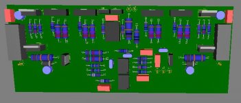
oke, on topic now, here is a design of the topamp, what i made for someone here.
good idee only I think co2 was some day in out admosfeer, al the oil was plants and animals, in the begin of the earts days there was a lot of co2 and
it was a paradise, but later, more and more plants and animals take co2 and
put that in the fosiles like oil.
so if we don,t stop oil use we go beack in time and that means less soil to live on, because everithing is started in the sea.
oke, on topic now, here is a design of the topamp, what i made for someone here.
Attachments
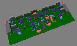
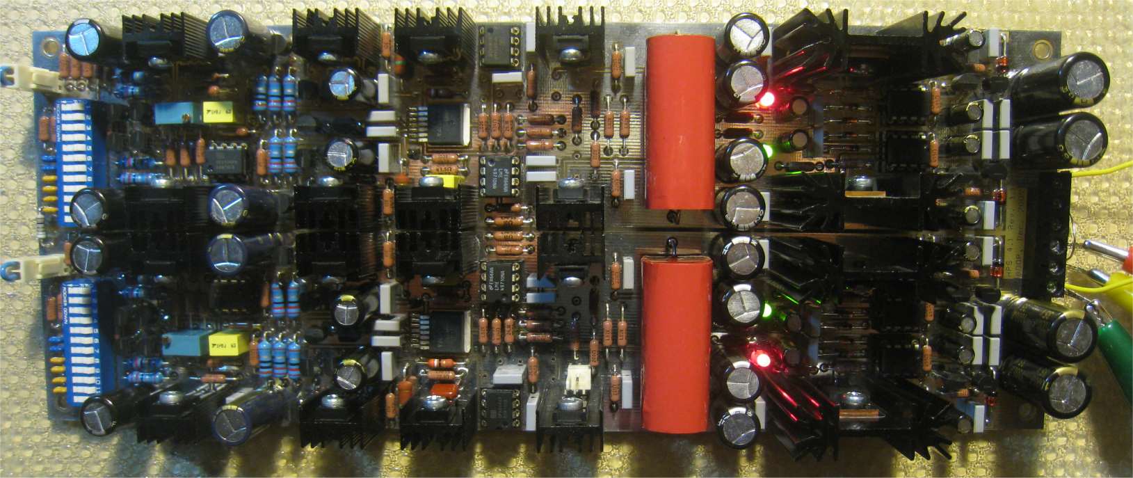
See the pictures.
This is a full bipolar version that uses Jung regulators and local bipolar buffers. It is also high impedance (default 47kohm), while the input current can be trimmed to under 50nA. No caps in the signal path.
Full measurements to follow, but here's the first noise measurement. RIAA correction is not installed, gain is a little over 80dB (will be 60dB @ 1KHz after RIAA correction). Bottom line - 0.28nV/rtHz.
Distortions are much better than in the HPS 3.1 JFET, I suppose because the large (8 x JFET) nonlinear Ciss is now missing. Overall, about 70ppm at all frequencies and output levels, up to +/-20V. HPS 4.1 has the same headroom of 32dB.
 .
.
This is a full bipolar version that uses Jung regulators and local bipolar buffers. It is also high impedance (default 47kohm), while the input current can be trimmed to under 50nA. No caps in the signal path.
Full measurements to follow, but here's the first noise measurement. RIAA correction is not installed, gain is a little over 80dB (will be 60dB @ 1KHz after RIAA correction). Bottom line - 0.28nV/rtHz.
Distortions are much better than in the HPS 3.1 JFET, I suppose because the large (8 x JFET) nonlinear Ciss is now missing. Overall, about 70ppm at all frequencies and output levels, up to +/-20V. HPS 4.1 has the same headroom of 32dB.
- Home
- Amplifiers
- Solid State
- Post your Solid State pics here